The 2004 Lincoln Aviator Obd2 Fuse Location is commonly found in the interior fuse panel, often located beneath the dashboard on the driver’s side. CAR-DIAGNOSTIC-TOOL.EDU.VN provides comprehensive diagnostics, repair guidance, and expert technical support, empowering technicians to quickly locate and address electrical issues. For advanced skills, we offer specialized technician training and remote support.
Contents
- 1. Decoding the 2004 Lincoln Aviator OBD2 Fuse Location
- 1.1. Common Locations of the OBD2 Fuse
- 1.2. Step-by-Step Guide to Find the OBD2 Fuse
- 1.3. Why is the OBD2 Fuse Important?
- 2. Comprehensive Fuse Box Diagrams for the 2004 Lincoln Aviator
- 2.1. Passenger Compartment Fuse Panel Diagram
- 2.1.1. Fuse Details and Functions
- 2.2. Power Distribution Box Diagram
- 2.2.1. Fuse Details and Functions
- 2.3. Fuse/Relay Location Diagram
- 2.3.1. Relay Details and Functions
- 2.4. Auxiliary Relay Box Diagram
- 2.4.1. Relay Details and Functions
- 2.5. Rear Relay Box Diagram
- 2.5.1. Relay Details and Functions
- 3. Troubleshooting Common OBD2 Fuse Problems
- 3.1. Symptoms of a Blown OBD2 Fuse
- 3.2. Diagnosing a Blown Fuse
- 3.3. Common Causes of a Blown OBD2 Fuse
- 3.4. Step-by-Step Fuse Replacement
- 3.5. Advanced Troubleshooting Techniques
- 4. Advanced Diagnostic Tools and Techniques
- 4.1. Importance of Using Quality Scan Tools
- 4.2. Overview of Diagnostic Tools
- 4.3. Using Scan Tools to Diagnose Electrical Issues
- 4.4. Benefits of Remote Diagnostic Support from CAR-DIAGNOSTIC-TOOL.EDU.VN
- 5. Preventative Maintenance for Your 2004 Lincoln Aviator
- 5.1. Importance of Regular Fuse Inspections
- 5.2. Maintaining Electrical Connections
- 5.3. Battery Maintenance Tips
- 5.4. Software Updates
- 6. Enhancing Your Skills with Technician Training
- 6.1. Overview of Technician Training Programs
- 6.2. Benefits of Participating in Training Programs
- 6.3. CAR-DIAGNOSTIC-TOOL.EDU.VN Training Modules
- 6.4. Certification Programs
- 7. Real-World Case Studies
- 7.1. Case Study 1: Intermittent OBD2 Port Failure
- 7.2. Case Study 2: Blown Fuse Caused by Short Circuit
- 7.3. Case Study 3: Communication Error Due to Faulty Module
- 8. Frequently Asked Questions (FAQs)
- 8.1. Where is the OBD2 port located in a 2004 Lincoln Aviator?
- 8.2. What type of fuse does the OBD2 port use?
- 8.3. How do I check if my OBD2 fuse is blown?
- 8.4. What causes an OBD2 fuse to blow?
- 8.5. Can I use a higher amperage fuse to prevent it from blowing again?
- 8.6. What should I do if the OBD2 fuse keeps blowing after replacement?
- 8.7. How can remote diagnostic support help me?
- 8.8. What are the benefits of technician training programs?
- 8.9. How can I enroll in CAR-DIAGNOSTIC-TOOL.EDU.VN training modules?
- 8.10. Are there any certifications available after completing the training programs?
- 9. Conclusion: Ensuring Reliable Diagnostics with CAR-DIAGNOSTIC-TOOL.EDU.VN
1. Decoding the 2004 Lincoln Aviator OBD2 Fuse Location
Are you struggling to locate the OBD2 fuse in your 2004 Lincoln Aviator? Knowing the exact location of this fuse is essential for diagnosing and resolving issues related to your vehicle’s onboard diagnostic system. This section will guide you through the common locations, diagnostic steps, and troubleshooting tips.
1.1. Common Locations of the OBD2 Fuse
The OBD2 fuse, responsible for powering the diagnostic port, is typically found in one of two locations:
- Interior Fuse Panel: Often situated beneath the dashboard on the driver’s side.
- Engine Compartment Fuse Box: Located near the engine, housing various critical fuses.
Check the owner’s manual for your 2004 Lincoln Aviator to pinpoint the precise location.
1.2. Step-by-Step Guide to Find the OBD2 Fuse
- Consult the Owner’s Manual: Your vehicle’s manual contains a detailed diagram of the fuse locations.
- Locate the Fuse Panels: Identify the interior fuse panel and the engine compartment fuse box.
- Inspect the Fuses: Look for a fuse labeled “OBD,” “Diagnostic,” or similar.
- Test the Fuse: Use a multimeter to check for continuity. If the fuse is blown, replace it with one of the same amperage.
1.3. Why is the OBD2 Fuse Important?
The OBD2 fuse ensures that the diagnostic port receives power, allowing technicians to connect scan tools and retrieve valuable information about the vehicle’s performance. Without a functioning OBD2 port, diagnosing issues becomes significantly more challenging.
2. Comprehensive Fuse Box Diagrams for the 2004 Lincoln Aviator
The 2004 Lincoln Aviator has five different fuse boxes, each serving specific functions. Detailed diagrams are crucial for accurate troubleshooting and repairs.
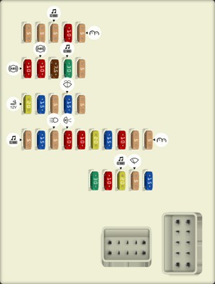
2.1. Passenger Compartment Fuse Panel Diagram
The passenger compartment fuse panel is typically located beneath the dashboard on the driver’s side. This panel houses fuses for various interior components.
 2004 Lincoln Aviator fuse box diagram Passenger compartment fuse panelPassenger compartment fuse panel diagram: This image highlights the layout of the fuses within the passenger compartment, crucial for identifying fuses related to interior components and systems.
 2.1.1. Fuse Details and Functions
| Fuse No. | Amperage | Description |
|---|---|---|
| 1 | 30A | Moonroof motor, Driver seat lumbar switch |
| 2 | 10A | VAPS module, Memory seat module, Body security module, Tire Pressure Monitor System (TPMS), Sunload/Autolamp sensor (SecuriLock LED) |
| 3 | 20A | Radio, Navigation system |
| 4 | 5A | Front wiper module |
| 5 | 15A | Flasher relay (turn/hazards) |
| 6 | 5A | Electronic Hidden Antenna Module (EHAM) (antenna amplifier), Radio, Moonroof motor, Driver window motor, Navigation |
| 7 | 15A | Heated mirrors, DEATC module |
| 8 | 5A | Daytime Running Lamps (DRL) module, Heated PCV valve |
| 9 | 10A | Back-up lamps (DTRS), Electrochromatic mirror |
| 10 | 10A | Heated backlight relay coil, Climate seat modules, Auxiliary A/C temperature blend/mode actuator, A/C clutch relay contact |
| 11 | 20A | Not used (spare) |
| 12 | 15A | Restraints module |
| 13 | 10A | Brake shift interlock |
| 14 | 5A | Not used (spare) |
| 15 | 5A | Instrument cluster, Rear wiper module, TPMS |
| 16 | 20A | Cigar lighter, OBD II |
| 17 | 15A | Delayed accessory relay coil, Battery saver relay coil and contacts |
| 18 | 5A | Not used (spare) |
| 19 | 15A | Washer pump |
| 20 | 5A | Shifter, Clock, Power mirror switch, DVD |
| 21 | 10A | Brake pressure switch (ABS), IVD switch, Flasher relay |
| 22 | 10A | ABS module |
| 23 | 7.5A | Liftgate release relay coil and contacts |
| 24 | 30A | Subwoofer, Navigation |
| 25 | 5A | Trailer tow battery charge relay coil |
| 26 | 5A | SecuriLock® transceiver |
| 27 | 5A | Rear park assist, VAPS module |
| 28 | 5A | Radio, Navigation |
| 29 | 10A | DTRS, Feed to Fuse 28 |
| 30 | 5A | Instrument cluster, Compass module, Auxiliary A/C relay coil |
2.2. Power Distribution Box Diagram
The power distribution box is located in the engine compartment. This box contains fuses and relays for critical vehicle systems.
 2004 Lincoln Aviator fuse box diagram Power distribution boxPower distribution box diagram: Illustrates the fuse and relay arrangement in the engine compartment, which controls major functions like starting, lighting, and braking systems.
2.2.1. Fuse Details and Functions
| Fuse No. | Type | Amperage | Description |
|---|---|---|---|
| 1 | FLF/PAL 293 | 60A | Power Junction Box (PJB) |
| 2 | FMX/JCase | 30A | Door locks (BSM) |
| 4 | FMX/JCase | 40A | Heated backlight/mirrors |
| 5 | FMX/JCase | 40A | Anti-lock Brake System (ABS) module (pump) |
| 6 | FMX/JCase | 60A | Delayed accessory |
| 7 | FMX/JCase | 20A | Daytime Running Lamps (DRL) module |
| 8 | FMX/JCase | 20A | Electric cooling fan |
| 9 | FMX/JCase | 20A | Headlamp switch |
| 10 | FMX/JCase | 30A | ABS module (valves) |
| 11 | FMX/JCase | 40A | PTEC relay contacts |
| 12 | FMX/JCase | 50A | Ignition/Starter relay |
| 13 | FMX/JCase | 40A | Trailer tow relays |
| 14 | MINI | 15A | Brake lamp feed |
| 15 | MINI | 10A | Keep alive power (PTEC/cluster/DEATC) |
| 16 | MINI | 20A | Power point #3 |
| 17 | MINI | 20A | Rear wiper module |
| 18 | MINI | 20A | 4×4 module |
| 19 | FMX/JCase | 30A | Driver window motor |
| 20 | FMX/JCase | 30A | Electric trailer brakes |
| 21 | FMX/JCase | 30A | Memory seat module |
| 22 | FMX/JCase | 20A | Main exterior lamps (low beam, high beam, fog) |
| 23 | FMX/JCase | 30A | Ignition switch |
| 24 | MINI | 20A | Horn relay |
| 25 | MINI | 20A | Power point #1 |
| 26 | MINI | 20A | Fuel pump relay contacts |
| 27 | MINI | 20A | Trailer tow lamps |
| 28 | MINI | 20A | Power point #2 |
| 29 | FLF/PAL 293 | 60A | PJB |
| 30 | FMX/JCase | 30A | Front wiper module |
| 31 | FMX/JCase | 30A | Climate-controlled seats modules |
| 32 | FMX/JCase | 30A | Passenger seat switch |
| 33 | FMX/JCase | 30A | Auxiliary blower motor |
| 34 | FMX/JCase | 20A | Right HID relay |
| 35 | FMX/JCase | 20A | Left HID relay |
| 36 | FMX/JCase | 40A | Blower motor |
| 37 | MINI | 15A | A/C clutch relay, TXV, Transmission, Speed control |
| 38 | MINI | 15A | HEGO, VMV, Canister vent, IMCC-LSRC, EGR module |
| 39 | MINI | 15A | Injectors |
| 40 | MINI | 15A | PTEC, Mass Air Flow (MAF) sensor, Fuel pump relay |
| 41 | MINI | 25A | Coil on plug, PTEC relay |
| 42 | MINI | 10A | Right low beam (halogen) |
| 43 | MINI | 10A | Left low beam (halogen) |
| 44 | MINI | 2A | Heated PCV valve (w/DRL only) |
| 45 | MINI | 2A | Brake Pressure Switch |
| 46 | MINI | 20A | High beams/Fog lamps |
| 47 | Relay | Horn relay | |
| 48 | Relay | Fuel pump relay | |
| 49 | Relay | High beam relay | |
| 50 | Relay | Fog lamp relay | |
| 52 | Relay | A/C clutch relay | |
| 53 | Relay | Trailer tow right turn relay | |
| 54 | Relay | Trailer tow left turn relay | |
| 55 | Relay | Blower motor relay | |
| 56 | Relay | Starter motor relay | |
| 57 | Relay | PTEC relay | |
| 58 | Relay | Ignition relay | |
| 59 | Relay | Driver brake applied relay | |
| 60 | Diode MINI | PCM diode | |
| 61 | Diode MINI | A/C clutch diode | |
| 62 | Circuit breaker MAXI | Power windows |
2.3. Fuse/Relay Location Diagram
This diagram provides specific locations for various fuses and relays within the vehicle.
 2004 Lincoln Aviator fuse box diagram Fuse/Relay LocationFuse/Relay Location diagram: Details the placement of specific fuses and relays throughout the vehicle, aiding in targeted troubleshooting of electrical components.
2.3.1. Relay Details and Functions
| Relay No. | Description |
|---|---|
| 1 | Flasher relay |
| 2 | Heated backlight relay |
| 3 | Delayed accessory relay |
| 4 | Open |
| 5 | Battery saver relay |
| 6 | Open |
| 7 | Open |
2.4. Auxiliary Relay Box Diagram
The auxiliary relay box contains additional relays that control specific vehicle functions.
 2004 Lincoln Aviator fuse box diagram Auxiliary relay boxAuxiliary relay box diagram: Shows the configuration of relays that support additional vehicle functionalities, essential for diagnosing issues in those specific systems.
2.4.1. Relay Details and Functions
| Relay No. | Description |
|---|---|
| 64 | Open |
| 65 | EDF relay (Full ISO) |
| 66 | Left HID relay (1/2 ISO) |
| 67 | Right HID relay (1/2 ISO) |
2.5. Rear Relay Box Diagram
The rear relay box is located in the rear of the vehicle and controls functions specific to that area.
 2004 Lincoln Aviator fuse box diagram Rear relay boxRear relay box diagram: Illustrates the layout of relays that manage rear vehicle functions, such as trailer towing and liftgate operations, valuable for resolving rear-related electrical problems.
2.5.1. Relay Details and Functions
| Relay/Diode No. | Description |
|---|---|
| 14 | Open |
| 15 | Trailer tow back-up lamps |
| 16 | Open |
| 17 | Open |
| 18 | Liftgate release solenoid |
| 19 | Trailer tow park lamps |
| 20 | Trailer tow battery charge |
| 21 | Open |
| 22 | Open |
| 23 | Open |
| Diode 3 | Open |
| Diode 4 | Open |
3. Troubleshooting Common OBD2 Fuse Problems
Experiencing issues with your OBD2 port? Here are common problems, diagnostic methods, and practical solutions to get your 2004 Lincoln Aviator back on track.
3.1. Symptoms of a Blown OBD2 Fuse
- No Power to the OBD2 Port: The scan tool fails to power up when connected.
- Inability to Communicate with the Vehicle’s Computer: Error messages indicate a communication failure.
- Check Engine Light Issues: The check engine light may not function correctly.
3.2. Diagnosing a Blown Fuse
- Visual Inspection: Check the fuse for a broken filament.
- Multimeter Test: Use a multimeter to test for continuity. A reading of 0 ohms indicates a blown fuse.
3.3. Common Causes of a Blown OBD2 Fuse
- Short Circuit: A wiring issue can cause excessive current draw.
- Overloaded Circuit: Connecting multiple devices to the OBD2 port simultaneously.
- Faulty Scan Tool: A malfunctioning scan tool can cause a surge in power.
3.4. Step-by-Step Fuse Replacement
- Turn Off the Vehicle: Ensure the ignition is off.
- Locate the Fuse Panel: Find the appropriate fuse panel using the diagrams provided earlier.
- Remove the Blown Fuse: Use a fuse puller to remove the damaged fuse.
- Install a New Fuse: Replace the fuse with one of the same amperage.
- Test the OBD2 Port: Connect a scan tool to verify functionality.
3.5. Advanced Troubleshooting Techniques
If the fuse continues to blow, there may be an underlying electrical issue. CAR-DIAGNOSTIC-TOOL.EDU.VN offers advanced diagnostics and troubleshooting support to identify and resolve these complex problems.
4. Advanced Diagnostic Tools and Techniques
To effectively diagnose and repair modern vehicles like the 2004 Lincoln Aviator, advanced diagnostic tools and techniques are essential.
4.1. Importance of Using Quality Scan Tools
High-quality scan tools provide accurate and reliable data, reducing diagnostic time and improving repair accuracy. Investing in professional-grade equipment is a smart choice for any technician.
4.2. Overview of Diagnostic Tools
- OBD2 Scanners: Basic tools for reading and clearing diagnostic trouble codes (DTCs).
- Advanced Scan Tools: Offer bidirectional control, live data streaming, and module programming capabilities.
- Multimeters: Essential for testing electrical circuits and components.
- Oscilloscopes: Used to analyze electrical signals and identify intermittent issues.
4.3. Using Scan Tools to Diagnose Electrical Issues
- Connect the Scan Tool: Plug the scan tool into the OBD2 port.
- Read DTCs: Identify any stored trouble codes.
- Analyze Live Data: Monitor real-time data to pinpoint malfunctioning components.
- Perform Bidirectional Tests: Activate and control specific components to verify their operation.
4.4. Benefits of Remote Diagnostic Support from CAR-DIAGNOSTIC-TOOL.EDU.VN
CAR-DIAGNOSTIC-TOOL.EDU.VN offers remote diagnostic support to assist technicians in resolving complex issues. Our experts can remotely access your scan tool data and provide guidance on troubleshooting and repair procedures.
5. Preventative Maintenance for Your 2004 Lincoln Aviator
Regular maintenance can prevent many common electrical issues and keep your 2004 Lincoln Aviator running smoothly.
5.1. Importance of Regular Fuse Inspections
Checking fuses regularly can help identify potential problems before they cause significant damage. Inspect fuses for corrosion, damage, and proper seating.
5.2. Maintaining Electrical Connections
Ensure all electrical connections are clean and secure. Use dielectric grease to protect connections from corrosion.
5.3. Battery Maintenance Tips
- Keep the Battery Clean: Remove any corrosion from the battery terminals.
- Test Battery Voltage: Regularly check the battery’s voltage to ensure it is within the proper range.
- Secure Battery Connections: Make sure the battery cables are securely attached.
5.4. Software Updates
Keep your vehicle’s software up to date to ensure optimal performance and prevent compatibility issues. Check with your dealer for available updates.
6. Enhancing Your Skills with Technician Training
Investing in technician training is a great way to enhance your diagnostic and repair skills. CAR-DIAGNOSTIC-TOOL.EDU.VN offers comprehensive training programs to help you stay ahead in the automotive industry.
6.1. Overview of Technician Training Programs
- Basic Electrical Diagnostics: Covers fundamental electrical concepts and diagnostic techniques.
- Advanced Diagnostics: Focuses on advanced scan tool functions, data analysis, and complex troubleshooting.
- Module Programming: Teaches technicians how to program and configure vehicle modules.
- Remote Diagnostics: Provides training on utilizing remote diagnostic tools and techniques.
6.2. Benefits of Participating in Training Programs
- Improved Diagnostic Accuracy: Reduce diagnostic time and improve the accuracy of your repairs.
- Increased Efficiency: Learn how to use advanced tools and techniques to streamline your workflow.
- Enhanced Knowledge: Stay up-to-date with the latest automotive technologies and repair procedures.
- Career Advancement: Enhance your career prospects and earning potential.
6.3. CAR-DIAGNOSTIC-TOOL.EDU.VN Training Modules
CAR-DIAGNOSTIC-TOOL.EDU.VN offers a variety of training modules designed to meet the needs of technicians at all skill levels. Our modules include:
- Module 1: Electrical Fundamentals
- Module 2: Scan Tool Diagnostics
- Module 3: Advanced Data Analysis
- Module 4: Module Programming
- Module 5: Remote Diagnostics
6.4. Certification Programs
Upon completion of our training programs, you can earn industry-recognized certifications that demonstrate your expertise and commitment to excellence.
7. Real-World Case Studies
Examining real-world case studies can provide valuable insights into diagnosing and resolving electrical issues in the 2004 Lincoln Aviator.
7.1. Case Study 1: Intermittent OBD2 Port Failure
Problem: The OBD2 port would intermittently lose power, preventing communication with the scan tool.
Diagnosis: After inspecting the fuse panel, a loose connection was found at the OBD2 fuse.
Solution: The fuse was reseated, and the connection was tightened, resolving the issue.
7.2. Case Study 2: Blown Fuse Caused by Short Circuit
Problem: The OBD2 fuse would repeatedly blow, even after replacement.
Diagnosis: A short circuit was identified in the wiring harness leading to the OBD2 port.
Solution: The damaged wiring was repaired, and the fuse was replaced, resolving the issue.
7.3. Case Study 3: Communication Error Due to Faulty Module
Problem: The scan tool could not communicate with the vehicle’s computer, even with a functioning OBD2 port.
Diagnosis: A faulty PCM (Powertrain Control Module) was identified as the cause of the communication error.
Solution: The PCM was replaced and programmed, restoring communication with the scan tool.
8. Frequently Asked Questions (FAQs)
8.1. Where is the OBD2 port located in a 2004 Lincoln Aviator?
The OBD2 port is typically located under the dashboard on the driver’s side.
8.2. What type of fuse does the OBD2 port use?
The OBD2 port typically uses a mini fuse. Refer to your owner’s manual for the specific amperage.
8.3. How do I check if my OBD2 fuse is blown?
Visually inspect the fuse for a broken filament or use a multimeter to test for continuity.
8.4. What causes an OBD2 fuse to blow?
Common causes include short circuits, overloaded circuits, and faulty scan tools.
8.5. Can I use a higher amperage fuse to prevent it from blowing again?
No, always use a fuse with the specified amperage to prevent damage to the electrical system.
8.6. What should I do if the OBD2 fuse keeps blowing after replacement?
There may be an underlying electrical issue. Seek professional diagnostic support from CAR-DIAGNOSTIC-TOOL.EDU.VN.
8.7. How can remote diagnostic support help me?
Remote diagnostic support allows experts to remotely access your scan tool data and provide guidance on troubleshooting and repair procedures.
8.8. What are the benefits of technician training programs?
Technician training programs improve diagnostic accuracy, increase efficiency, enhance knowledge, and advance your career.
8.9. How can I enroll in CAR-DIAGNOSTIC-TOOL.EDU.VN training modules?
Visit CAR-DIAGNOSTIC-TOOL.EDU.VN or contact our support team for enrollment information.
8.10. Are there any certifications available after completing the training programs?
Yes, we offer industry-recognized certifications upon completion of our training programs.
9. Conclusion: Ensuring Reliable Diagnostics with CAR-DIAGNOSTIC-TOOL.EDU.VN
Knowing the 2004 Lincoln Aviator OBD2 fuse location is critical for effective vehicle diagnostics. CAR-DIAGNOSTIC-TOOL.EDU.VN not only provides the necessary information but also offers advanced diagnostic tools, remote support, and comprehensive technician training to ensure you are well-equipped to handle any automotive electrical issue. By staying proactive with maintenance and continuously improving your skills, you can keep your Lincoln Aviator running smoothly and efficiently.
Ready to take your diagnostic skills to the next level? Contact CAR-DIAGNOSTIC-TOOL.EDU.VN today for expert guidance, cutting-edge tools, and comprehensive training programs. Our team is here to support you with all your automotive diagnostic needs. Reach out now via WhatsApp at +1 (641) 206-8880 or visit our office at 1100 Congress Ave, Austin, TX 78701, United States. Don’t wait, unlock your potential with CAR-DIAGNOSTIC-TOOL.EDU.VN and drive your career forward!