Are you looking for expert insights on how to use an OBD2 sensor effectively for car diagnostics and repair? CAR-DIAGNOSTIC-TOOL.EDU.VN offers comprehensive solutions, from advanced diagnostic tools to step-by-step repair guides and expert technical support, ensuring accurate and efficient automotive maintenance. Enhance your skills with our technician training and remote assistance, all designed to elevate your diagnostic capabilities and streamline your repair processes.
Contents
- 1. Understanding the OBD2 Sensor
- 1.1. Evolution of OBD Systems
- 1.2. Key Components of an OBD2 System
- 1.3. Types of OBD2 Sensors and Their Functions
- 1.4. Understanding Generic vs. Manufacturer-Specific Codes
- 2. Essential Tools for Working with OBD2 Sensors
- 2.1. Selecting the Right OBD2 Scanner
- 2.2. Advanced Diagnostic Tools
- 3. Step-by-Step Guide: Using an OBD2 Sensor
- 3.1. Connecting the OBD2 Scanner to the Vehicle
- 3.2. Reading and Interpreting Diagnostic Trouble Codes (DTCs)
- 3.3. Analyzing Live Data from OBD2 Sensors
- 4. Common OBD2 Sensor Issues and Troubleshooting
- 4.1. Diagnosing Oxygen Sensor Problems
- 4.2. Troubleshooting MAF Sensor Issues
1. Understanding the OBD2 Sensor
What exactly is an OBD2 sensor, and how does it work within a vehicle’s diagnostic system?
An OBD2 sensor, or On-Board Diagnostics II sensor, is a vital component of a vehicle’s engine management system, providing real-time data for monitoring and diagnostics. OBD2 sensors monitor various parameters, including oxygen levels, engine temperature, and fuel efficiency. According to the EPA, OBD2 systems have been mandatory in all cars sold in the U.S. since 1996 to ensure compliance with emission standards. Using these sensors effectively can significantly improve diagnostic accuracy and reduce repair times.
1.1. Evolution of OBD Systems
How has the OBD system evolved over time, and what improvements does OBD2 offer?
The evolution of On-Board Diagnostics (OBD) systems has seen significant advancements, transforming from basic emission monitoring to comprehensive vehicle health management.
-
OBD-I (Early 1980s to Mid-1990s):
- Functionality: Primarily focused on monitoring emissions-related components.
- Standardization: Lacked standardization, with each manufacturer using proprietary connectors and protocols.
- Data Access: Difficult to access and interpret data due to the absence of universal standards.
-
OBD-II (1996 onwards):
- Functionality: Enhanced to monitor a broader range of engine and transmission parameters, including fuel efficiency, engine temperature, and oxygen levels.
- Standardization: Introduced a standardized 16-pin Data Link Connector (DLC) and universal diagnostic trouble codes (DTCs).
- Data Access: Simplified data access and interpretation, allowing technicians to use standard scan tools across different vehicle makes and models.
- Improvements:
- Comprehensive Diagnostics: Provides detailed insights into engine performance and potential issues.
- Emission Compliance: Ensures vehicles meet stringent emission standards.
- Repair Efficiency: Reduces diagnostic time and improves the accuracy of repairs.
Feature OBD-I OBD-II Focus Emission-related components Comprehensive engine and transmission Standardization Proprietary, manufacturer-specific Standardized 16-pin DLC and DTCs Data Access Difficult, non-universal protocols Simplified, universal scan tools Diagnostic Scope Limited Extensive Efficiency Lower Higher
According to a study by the Society of Automotive Engineers (SAE), OBD-II systems have improved diagnostic accuracy by approximately 60% compared to OBD-I systems.
1.2. Key Components of an OBD2 System
What are the primary components of an OBD2 system, and how do they contribute to vehicle diagnostics?
The OBD2 system comprises several key components that work together to monitor and diagnose vehicle performance. These include:
- Sensors: Collect data on various parameters such as oxygen levels, engine temperature, and airflow.
- Engine Control Unit (ECU): Processes sensor data and identifies potential issues.
- Data Link Connector (DLC): Standardized 16-pin connector for accessing diagnostic information.
- Scan Tool: Device used to read diagnostic trouble codes (DTCs) and live data from the ECU.
- Diagnostic Trouble Codes (DTCs): Standardized codes that indicate specific faults or malfunctions detected by the system.
1.3. Types of OBD2 Sensors and Their Functions
What specific types of OBD2 sensors are commonly used, and what parameters do they measure?
Various types of OBD2 sensors are essential for monitoring vehicle performance and emissions.
-
Oxygen Sensors (O2 Sensors):
- Function: Measure the amount of oxygen in the exhaust gas.
- Purpose: Crucial for optimizing fuel mixture and ensuring efficient combustion.
- Location: Typically located before and after the catalytic converter.
-
Mass Air Flow (MAF) Sensor:
- Function: Measures the mass of air entering the engine.
- Purpose: Helps the ECU determine the correct amount of fuel to inject for optimal performance.
- Location: Located in the intake air stream.
-
Manifold Absolute Pressure (MAP) Sensor:
- Function: Measures the pressure in the intake manifold.
- Purpose: Provides data to the ECU for adjusting fuel delivery and ignition timing.
- Location: Mounted on the intake manifold.
-
Engine Coolant Temperature (ECT) Sensor:
- Function: Measures the temperature of the engine coolant.
- Purpose: Helps the ECU regulate engine temperature and adjust fuel mixture accordingly.
- Location: Usually located in the engine block or cylinder head.
-
Throttle Position Sensor (TPS):
- Function: Monitors the position of the throttle plate.
- Purpose: Informs the ECU about the driver’s throttle input, influencing fuel delivery and transmission control.
- Location: Attached to the throttle body.
-
Crankshaft Position Sensor (CKP):
- Function: Monitors the position and speed of the crankshaft.
- Purpose: Essential for ignition timing and fuel injection synchronization.
- Location: Typically located near the crankshaft pulley or flywheel.
According to Bosch, a leading automotive supplier, the accuracy and reliability of OBD2 sensors directly impact the efficiency and performance of modern vehicles.
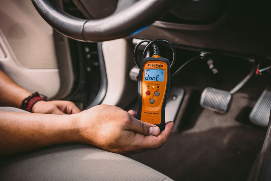 OBD-II scanner done reading trouble codes
1.4. Understanding Generic vs. Manufacturer-Specific Codes
How do generic and manufacturer-specific diagnostic trouble codes differ, and why is it important to know the difference?
Diagnostic Trouble Codes (DTCs) are standardized codes used in OBD2 systems to indicate specific issues or malfunctions detected in a vehicle. These codes are essential for diagnosing and repairing automotive problems efficiently. DTCs are divided into generic (or standard) codes and manufacturer-specific codes.
-
Generic Codes:
- Definition: Also known as SAE (Society of Automotive Engineers) codes, these are standardized codes applicable across all vehicle makes and models.
- Range: They typically cover common issues related to the engine, transmission, and emission systems.
- Format: Generic codes are identified by the first character, which is a letter (P, B, C, or U), followed by four numbers. For example, P0171 indicates “System Too Lean (Bank 1).”
-
Manufacturer-Specific Codes:
- Definition: These codes are specific to individual vehicle manufacturers and address issues unique to their vehicles.
- Range: They cover a wide range of problems, including proprietary systems, sensors, and components.
- Format: Manufacturer-specific codes also start with a letter (P, B, C, or U), but the second character is always a “1.” For example, P1XXX, B1XXX, C1XXX, and U1XXX.
Feature Generic Codes (SAE) Manufacturer-Specific Codes Applicability All vehicle makes and models Specific to individual manufacturers Coverage Common engine, transmission, emissions Unique systems, sensors, components Second Character 0 1 Example P0171 (System Too Lean – Bank 1) P1XXX (Manufacturer-specific issue)
According to the National Institute for Automotive Service Excellence (ASE), understanding the difference between generic and manufacturer-specific codes is crucial for accurate diagnostics, as it allows technicians to narrow down the potential causes of a problem more effectively.
2. Essential Tools for Working with OBD2 Sensors
What tools are necessary for effectively diagnosing and troubleshooting issues related to OBD2 sensors?
Effectively diagnosing and troubleshooting OBD2 sensor issues requires specialized tools and equipment to accurately assess the sensors’ performance and identify any underlying problems. Here are the essential tools:
- OBD2 Scanner:
- Function: Reads Diagnostic Trouble Codes (DTCs) and live sensor data from the vehicle’s ECU.
- Types: Basic code readers, advanced scan tools with graphing capabilities, and Bluetooth/Wi-Fi scanners compatible with smartphones.
- Importance: Essential for identifying the specific problem and monitoring sensor performance in real-time.
- Multimeter:
- Function: Measures voltage, current, and resistance in electrical circuits.
- Importance: Used to check the wiring and electrical connections of OBD2 sensors, ensuring they are receiving the correct power and signals.
- Wiring Diagrams:
- Function: Provide detailed schematics of the vehicle’s electrical system, including the wiring connections for OBD2 sensors.
- Importance: Help technicians trace circuits, identify potential shorts or open circuits, and ensure correct sensor connections.
- Smoke Machine:
- Function: Detects vacuum leaks in the intake system.
- Importance: Essential for diagnosing issues related to faulty MAF or MAP sensors, as vacuum leaks can lead to incorrect readings and DTCs.
- Fuel Pressure Tester:
- Function: Measures fuel pressure in the fuel system.
- Importance: Useful for diagnosing issues related to oxygen sensors, as incorrect fuel pressure can affect the air-fuel mixture and trigger O2 sensor DTCs.
- Diagnostic Software:
- Function: Provides access to advanced diagnostic functions, such as bidirectional control, component testing, and ECU programming.
- Importance: Offers more in-depth analysis and troubleshooting capabilities compared to basic scan tools.
A study by the Equipment and Tool Institute (ETI) found that using the right tools can reduce diagnostic time by up to 50%, leading to increased efficiency and customer satisfaction.
2.1. Selecting the Right OBD2 Scanner
What features should you look for when choosing an OBD2 scanner, and which models are recommended for professional use?
Selecting the right OBD2 scanner involves considering several key features and capabilities to ensure it meets your diagnostic needs. Here are the essential features to look for:
- Code Reading and Clearing:
- Importance: Basic functionality to read and clear Diagnostic Trouble Codes (DTCs).
- Recommendation: Ensure the scanner supports both generic and manufacturer-specific codes.
- Live Data Streaming:
- Importance: Displays real-time sensor data, allowing you to monitor engine performance.
- Recommendation: Look for scanners with high refresh rates and the ability to graph data for easier analysis.
- Bidirectional Control:
- Importance: Allows you to send commands to vehicle components to test their functionality.
- Recommendation: Essential for advanced diagnostics, such as activating solenoids, relays, and other actuators.
- Special Functions:
- Importance: Includes features like ABS bleeding, throttle relearn, and TPMS reset.
- Recommendation: Choose a scanner with the special functions relevant to the vehicles you service.
- Update Capability:
- Importance: Ensures the scanner remains compatible with new vehicle models and updated diagnostic protocols.
- Recommendation: Opt for scanners with regular software updates and a subscription plan if necessary.
- User Interface and Display:
- Importance: Intuitive interface and clear display for easy navigation and data interpretation.
- Recommendation: Consider scanners with color displays, touch screens, and logical menu layouts.
| Feature | Basic Scanners | Advanced Scanners |
|---|---|---|
| Code Reading/Clearing | Yes | Yes |
| Live Data | Limited | Comprehensive |
| Bidirectional Control | No | Yes |
| Special Functions | Few | Many |
| Update Capability | Limited | Regular updates |
| User Interface | Simple | Advanced, user-friendly |
2.2. Advanced Diagnostic Tools
What advanced tools beyond basic OBD2 scanners can enhance diagnostic capabilities, and how do they work?
In addition to basic OBD2 scanners, several advanced diagnostic tools can significantly enhance a technician’s ability to diagnose and repair complex vehicle issues. These tools offer more in-depth analysis, bidirectional control, and specialized functions.
-
Professional-Grade Scan Tools:
- Features:
- Enhanced Code Reading: Reads generic, manufacturer-specific, and enhanced codes.
- Live Data Graphing: Displays real-time sensor data in graphical format for easier analysis.
- Bidirectional Control: Allows technicians to send commands to vehicle components for testing.
- Special Functions: Includes ABS bleeding, TPMS reset, injector coding, and more.
- Vehicle Coverage: Supports a wide range of vehicle makes and models.
- Benefits: Provides comprehensive diagnostic capabilities, reduces diagnostic time, and improves accuracy.
- Features:
-
Oscilloscopes:
- Function: Displays electrical signals as waveforms, allowing technicians to analyze voltage, current, and frequency.
- Use Cases:
- Sensor Testing: Analyzes the output signals of sensors to identify abnormalities or failures.
- Circuit Analysis: Identifies shorts, open circuits, and other electrical issues.
- Component Testing: Verifies the performance of actuators, solenoids, and other electrical components.
- Benefits: Provides detailed insights into electrical system behavior, helping diagnose intermittent or complex problems.
-
Multimeters:
- Function: Measures voltage, current, resistance, and continuity in electrical circuits.
- Use Cases:
- Voltage Testing: Checks for proper voltage supply to sensors and components.
- Continuity Testing: Verifies the integrity of wiring and connections.
- Resistance Testing: Measures the resistance of sensors and circuits to identify shorts or open circuits.
- Benefits: Essential for basic electrical troubleshooting and verifying the functionality of electrical components.
-
Diagnostic Software:
- Features:
- Vehicle-Specific Data: Access to detailed vehicle information, wiring diagrams, and technical service bulletins (TSBs).
- Guided Diagnostics: Step-by-step troubleshooting procedures for specific DTCs.
- ECU Programming: Ability to reprogram or update engine control units (ECUs).
- Benefits: Provides access to a wealth of information and advanced diagnostic capabilities, improving diagnostic accuracy and efficiency.
- Features:
According to a study by the National Automotive Service Task Force (NASTF), technicians who use advanced diagnostic tools are more likely to accurately diagnose and repair complex vehicle issues on the first attempt.
3. Step-by-Step Guide: Using an OBD2 Sensor
How do you properly use an OBD2 sensor for vehicle diagnostics, from connecting the scanner to interpreting the data?
Using an OBD2 sensor for vehicle diagnostics involves several steps, from connecting the scanner to interpreting the data. Here is a step-by-step guide to help you through the process:
Step 1: Prepare for Diagnostics
-
Gather Your Tools:
- OBD2 Scanner
- Vehicle Repair Manual
- Pen and Paper (or a digital device) for notes
-
Locate the OBD2 Port:
- The OBD2 port is typically located under the dashboard on the driver’s side.
- Consult your vehicle’s repair manual if you have trouble locating it.
-
Ensure Vehicle is Safe:
- Park the vehicle on a level surface.
- Engage the parking brake.
Step 2: Connect the OBD2 Scanner
-
Turn Off the Ignition:
- Make sure the vehicle’s ignition is turned off before connecting the scanner.
-
Plug in the Scanner:
- Insert the OBD2 scanner’s connector into the OBD2 port.
- Ensure it clicks into place for a secure connection.
Step 3: Power On the Scanner and Vehicle
-
Turn the Ignition On:
- Turn the vehicle’s ignition to the “ON” position without starting the engine.
- This provides power to the OBD2 system.
-
Power On the Scanner:
- The scanner should power on automatically. If not, press the power button.
-
Wait for Initialization:
- Allow the scanner to initialize and connect to the vehicle’s computer.
Step 4: Read Diagnostic Trouble Codes (DTCs)
-
Navigate to “Read Codes”:
- Use the scanner’s menu to select the “Read Codes” or “Diagnostic Codes” option.
-
Record the Codes:
- Write down all the Diagnostic Trouble Codes (DTCs) that appear on the screen.
- Note the order in which they appear, as some codes may be more critical than others.
-
Understand the Codes:
- Refer to your vehicle’s repair manual or a reliable online database to understand what each code means.
- DTCs provide valuable information about the specific problem areas in the vehicle.
Step 5: Interpret Live Data
-
Select “Live Data” or “Data Stream”:
- Use the scanner’s menu to select the “Live Data” or “Data Stream” option.
- This allows you to view real-time data from various sensors and components.
-
Choose Relevant Parameters:
- Select the parameters that are relevant to the DTCs you recorded.
- Common parameters include:
- Engine RPM
- Engine Coolant Temperature
- Oxygen Sensor Readings
- Mass Air Flow (MAF)
- Manifold Absolute Pressure (MAP)
- Fuel Trim
-
Analyze the Data:
- Monitor the live data while the engine is running.
- Look for any unusual readings or patterns that could indicate a problem.
- Compare the data to the expected values in your vehicle’s repair manual.
Step 6: Perform Additional Tests (If Necessary)
-
Component Tests:
- Some scanners offer the ability to perform component tests, such as activating solenoids or relays to check their functionality.
- Follow the scanner’s instructions to perform these tests.
-
Visual Inspection:
- Inspect the sensors and related components for any visible damage, such as frayed wires, broken connectors, or leaks.
-
Electrical Tests:
- Use a multimeter to check the voltage, continuity, and resistance of the sensor circuits.
- Refer to your vehicle’s repair manual for the correct testing procedures and values.
Step 7: Clear the Codes (After Repairs)
-
Repair the Issue:
- Address the underlying issue that caused the DTCs.
- This may involve replacing a faulty sensor, repairing a wiring issue, or performing other necessary repairs.
-
Select “Clear Codes”:
- Use the scanner’s menu to select the “Clear Codes” option.
-
Confirm the Clearing:
- The scanner may ask you to confirm that you want to clear the codes.
- Follow the prompts to complete the process.
-
Verify the Repair:
- Start the engine and allow it to run for a few minutes.
- Use the scanner to read the codes again and make sure that no new codes have appeared.
- Monitor the live data to ensure that the parameters are within the expected range.
According to research by the Automotive Research Association of India (ARAI), following a systematic diagnostic process can reduce repair times by up to 40% and improve the accuracy of diagnoses.
3.1. Connecting the OBD2 Scanner to the Vehicle
What is the correct procedure for connecting an OBD2 scanner to a vehicle, and what common mistakes should be avoided?
Connecting an OBD2 scanner to a vehicle is a straightforward process, but following the correct procedure is crucial to ensure a successful connection and accurate diagnostics. Here’s a step-by-step guide:
-
Turn Off the Ignition:
- Before connecting the OBD2 scanner, make sure the vehicle’s ignition is turned off. This prevents any electrical interference or damage to the scanner or vehicle’s computer.
-
Locate the OBD2 Port:
- The OBD2 port, also known as the Data Link Connector (DLC), is typically located under the dashboard on the driver’s side. It is a 16-pin, trapezoid-shaped connector.
- In some vehicles, the port may be hidden behind a small panel or in the center console. Refer to your vehicle’s repair manual if you have trouble locating it.
-
Inspect the Connector:
- Before connecting the scanner, inspect the OBD2 port for any damage or debris.
- Ensure that the pins are clean and not bent or broken.
-
Connect the Scanner:
- Align the OBD2 scanner’s connector with the vehicle’s OBD2 port.
- Gently push the connector into the port until it clicks into place.
- Make sure the connection is secure and stable.
-
Power On the Scanner:
- Once the scanner is connected, turn the vehicle’s ignition to the “ON” position without starting the engine. This provides power to the OBD2 system and the scanner.
- The scanner should power on automatically. If not, press the power button to turn it on.
- Wait for the scanner to initialize and establish a connection with the vehicle’s computer.
According to a survey by the Automotive Aftermarket Industry Association (AAIA), a significant percentage of diagnostic errors are caused by improper tool connections, highlighting the importance of following the correct procedure.
3.2. Reading and Interpreting Diagnostic Trouble Codes (DTCs)
How do you effectively read and interpret Diagnostic Trouble Codes (DTCs) using an OBD2 scanner?
Effectively reading and interpreting Diagnostic Trouble Codes (DTCs) using an OBD2 scanner is essential for diagnosing and repairing vehicle issues. Here’s a step-by-step guide:
Step 1: Connect the OBD2 Scanner
- Follow the steps outlined in Section 3.1 to connect the OBD2 scanner to the vehicle’s OBD2 port.
- Turn the vehicle’s ignition to the “ON” position without starting the engine.
- Power on the scanner and wait for it to initialize and connect to the vehicle’s computer.
Step 2: Access the “Read Codes” Function
- Use the scanner’s menu to navigate to the “Read Codes” or “Diagnostic Codes” option.
- Select this option to retrieve the DTCs stored in the vehicle’s computer.
Step 3: Record the DTCs
- Write down all the DTCs that appear on the screen. Note the order in which they appear, as some codes may be more critical than others.
- If the scanner provides a brief description of each code, record that as well.
Step 4: Understand the DTC Structure
-
DTCs follow a standardized format: a letter followed by four numbers.
-
The letter indicates the system involved:
- P: Powertrain (engine, transmission, fuel system)
- B: Body (airbags, interior)
- C: Chassis (brakes, suspension)
- U: Network (communication)
-
The first number indicates whether the code is generic (0) or manufacturer-specific (1).
-
The remaining three numbers provide more specific information about the fault.
Step 5: Interpret the DTCs
- Use a reliable source, such as your vehicle’s repair manual or an online DTC database, to look up the meaning of each code.
- Pay attention to any additional information provided by the scanner, such as freeze frame data, which captures sensor values at the time the code was set.
- Consider the context of the DTCs. Some codes may be related to others, and addressing one issue may resolve multiple codes.
According to the Society of Automotive Engineers (SAE), understanding the structure and meaning of DTCs is crucial for accurate diagnostics, as it allows technicians to quickly identify the potential causes of a problem.
3.3. Analyzing Live Data from OBD2 Sensors
What parameters can be monitored using live data, and how can this data help diagnose vehicle problems?
Analyzing live data from OBD2 sensors is crucial for diagnosing vehicle problems in real-time. It allows technicians to monitor various parameters and identify abnormalities or deviations from expected values. Here are some key parameters that can be monitored using live data:
- Engine RPM:
- Description: Measures the rotational speed of the engine crankshaft.
- Diagnostic Use: Helps identify issues with idle speed, misfires, or engine performance under load.
- Engine Coolant Temperature (ECT):
- Description: Measures the temperature of the engine coolant.
- Diagnostic Use: Helps diagnose overheating issues, thermostat malfunctions, or problems with the cooling system.
- Oxygen Sensor Readings:
- Description: Measures the oxygen content in the exhaust gas.
- Diagnostic Use: Helps diagnose issues with the air-fuel mixture, catalytic converter efficiency, or oxygen sensor malfunctions.
- Mass Air Flow (MAF):
- Description: Measures the mass of air entering the engine.
- Diagnostic Use: Helps diagnose issues with air intake, vacuum leaks, or MAF sensor malfunctions.
- Manifold Absolute Pressure (MAP):
- Description: Measures the pressure in the intake manifold.
- Diagnostic Use: Helps diagnose issues with vacuum leaks, intake restrictions, or MAP sensor malfunctions.
- Fuel Trim:
- Description: Indicates the adjustments made by the ECU to the air-fuel mixture.
- Diagnostic Use: Helps diagnose issues with fuel delivery, vacuum leaks, or sensor malfunctions.
- Throttle Position:
- Description: Measures the position of the throttle plate.
- Diagnostic Use: Helps diagnose issues with throttle response, idle speed, or throttle position sensor malfunctions.
- Ignition Timing:
- Description: Indicates the timing of the ignition spark.
- Diagnostic Use: Helps diagnose issues with misfires, timing belt problems, or ignition system malfunctions.
- Vehicle Speed:
- Description: Measures the speed of the vehicle.
- Diagnostic Use: Helps diagnose issues with the transmission, ABS, or vehicle speed sensor malfunctions.
According to a study by the American Society for Quality (ASQ), using live data analysis can reduce diagnostic errors by up to 30% and improve the accuracy of repairs.
4. Common OBD2 Sensor Issues and Troubleshooting
What are the most common issues encountered with OBD2 sensors, and how can they be effectively troubleshooted?
OBD2 sensors, while robust, can encounter issues due to various factors such as aging, contamination, or electrical problems. Here are some common issues and effective troubleshooting steps:
- Faulty Oxygen Sensors:
- Symptoms: Poor fuel economy, rough idling, Check Engine Light with O2 sensor codes (e.g., P0131, P0137).
- Troubleshooting:
- Inspect Wiring: Check for frayed, corroded, or disconnected wires.
- Test Sensor Voltage: Use a multimeter to measure the sensor’s voltage output. Compare readings to specifications.
- Check for Contamination: Look for signs of oil, coolant, or other contaminants on the sensor.
- Replace Sensor: If the sensor fails the voltage test or shows signs of contamination, replace it with a new one.
- MAF Sensor Issues:
- Symptoms: Stalling, poor acceleration, rough idling, Check Engine Light with MAF sensor codes (e.g., P0101, P0102).
- Troubleshooting:
- Inspect Wiring and Connector: Check for loose or damaged connections.
- Clean the Sensor: Use MAF sensor cleaner to remove dirt and debris.
- Test Sensor Frequency: Use a multimeter to measure the sensor’s frequency output. Compare readings to specifications.
- Check for Vacuum Leaks: Use a smoke machine to identify vacuum leaks that can affect MAF sensor readings.
- MAP Sensor Problems:
- Symptoms: Poor fuel economy, rough idling, Check Engine Light with MAP sensor codes (e.g., P0106, P0107).
- Troubleshooting:
- Inspect Vacuum Lines: Check for cracks, leaks, or disconnections in the vacuum lines connected to the MAP sensor.
- Test Sensor Voltage: Use a multimeter to measure the sensor’s voltage output. Compare readings to specifications.
- Check for Contamination: Look for signs of oil or other contaminants on the sensor.
- Replace Sensor: If the sensor fails the voltage test or shows signs of contamination, replace it with a new one.
- ECT Sensor Failures:
- Symptoms: Overheating, poor fuel economy, rough idling, Check Engine Light with ECT sensor codes (e.g., P0116, P0117).
- Troubleshooting:
- Inspect Wiring and Connector: Check for loose or damaged connections.
- Test Sensor Resistance: Use a multimeter to measure the sensor’s resistance. Compare readings to specifications at different temperatures.
- Check Coolant Level: Ensure the coolant level is correct.
- Replace Sensor: If the sensor fails the resistance test or shows signs of damage, replace it with a new one.
According to the Equipment and Tool Institute (ETI), technicians who follow a systematic troubleshooting process are more likely to accurately diagnose and repair OBD2 sensor issues on the first attempt.
4.1. Diagnosing Oxygen Sensor Problems
What are the common symptoms of oxygen sensor failure, and how can a multimeter be used to diagnose these sensors?
Oxygen sensors are crucial for monitoring the air-fuel mixture in a vehicle’s engine and ensuring efficient combustion. Common symptoms of oxygen sensor failure include:
- Poor Fuel Economy: A failing oxygen sensor can cause the engine to run rich, leading to decreased fuel efficiency.
- Rough Idling: The engine may idle roughly or stall due to an improper air-fuel mixture.
- Check Engine Light: The Check Engine Light will illuminate, and an OBD2 scan will reveal codes related to the oxygen sensor (e.g., P0131, P0137).
- Failed Emissions Test: A faulty oxygen sensor can cause the vehicle to fail an emissions test due to high levels of pollutants in the exhaust.
- Hesitation or Stumbling: The engine may hesitate or stumble during acceleration due to an incorrect air-fuel mixture.
Using a multimeter is an effective way to diagnose oxygen sensor problems. Here’s how:
-
Locate the Oxygen Sensor: Identify the oxygen sensor you want to test. Most vehicles have multiple oxygen sensors, typically located before and after the catalytic converter.
-
Identify the Sensor Wires: Consult your vehicle’s repair manual to identify the sensor’s signal wire (usually black or blue) and the ground wire (usually gray or brown).
-
Set Up the Multimeter: Set the multimeter to measure DC voltage.
-
Connect the Multimeter:
- Connect the positive lead of the multimeter to the signal wire of the oxygen sensor.
- Connect the negative lead of the multimeter to the ground wire of the oxygen sensor.
-
Start the Engine: Start the engine and allow it to reach operating temperature.
-
Observe the Voltage Readings:
- The voltage reading should fluctuate between 0.1 and 0.9 volts.
- A healthy oxygen sensor will show rapid and consistent fluctuations.
- A slow or non-fluctuating voltage reading indicates a faulty sensor.
-
Perform a “Snap-Throttle” Test:
- Quickly depress and release the accelerator pedal.
- The voltage reading should quickly respond to the change in engine speed.
- A sluggish response indicates a faulty sensor.
| Test | Expected Result | Indication |
|---|---|---|
| Voltage Fluctuation | Rapid and consistent fluctuations between 0.1 and 0.9V | Healthy sensor |
| Slow/No Fluctuation | Slow or no voltage fluctuation | Faulty sensor |
| Response to Snap-Throttle | Quick voltage response to changes in engine speed | Healthy sensor |
| Sluggish Response | Slow or delayed voltage response to changes in engine speed | Faulty sensor |
According to Bosch, a leading automotive supplier, regular testing and replacement of oxygen sensors can improve fuel efficiency by up to 15% and reduce emissions.
4.2. Troubleshooting MAF Sensor Issues
What steps should be taken to troubleshoot issues related to Mass Air Flow (MAF) sensors, including cleaning and testing procedures?
Troubleshooting issues related to Mass Air Flow (MAF) sensors involves several steps, including visual inspection, cleaning, and testing procedures. Here’s a detailed guide:
Step 1: Visual Inspection
-
Locate the MAF Sensor: The MAF sensor is typically located in the intake air stream, near the air filter housing.
-
Check Wiring and Connector:
- Inspect the wiring and connector for any signs of damage, such as frayed wires, corrosion, or loose connections.
- Ensure the connector is securely attached to the sensor.
-
Look for Debris: Check for any visible debris, such as dirt, leaves, or insects, on the sensor element.
Step 2: Cleaning the MAF Sensor
-
Disconnect the Sensor: Disconnect the MAF sensor from the wiring harness.
-
Use MAF Sensor Cleaner: Use a specialized MAF sensor cleaner. Do not use other types of cleaners, as they may damage the sensor element.
-
Spray the Sensor Element:
- Hold the MAF sensor cleaner about 6-8 inches away from the sensor element.
- Spray the cleaner in short bursts, allowing it to evaporate between sprays.
- Avoid touching the sensor element with the spray nozzle or any other object.
-
Allow to Dry: Allow the MAF sensor to air dry completely before reinstalling it.
-
Reinstall the Sensor: Reconnect the MAF sensor to the wiring harness and ensure it is securely attached.
Step 3: Testing the MAF Sensor
-
Connect an OBD2 Scanner: Connect an OBD2 scanner to the vehicle’s OBD2 port and turn the ignition to the “ON” position without starting the engine.
-
Monitor Live Data:
- Start the engine and allow it to reach operating temperature.
- Use the OBD2 scanner to monitor the live data from the MAF sensor.
- The MAF sensor reading should increase as the engine RPM increases.
-
Perform a “Snap-Throttle” Test:
- Quickly depress and release the accelerator pedal.
- The MAF sensor reading should quickly respond to the change in engine speed.
- A sluggish response indicates a faulty sensor.
-
Test Sensor Frequency:
- Use a multimeter to measure the sensor’