Ecu P2p Vtec is a crucial component for optimizing engine performance in Honda vehicles, and CAR-DIAGNOSTIC-TOOL.EDU.VN is here to provide you with the diagnostic tools, repair guides, and technical support needed to master its wiring and troubleshooting. We also offer technician training and remote assistance.
Contents
- 1. What is ECU P2P VTEC?
- 1.1. Understanding the VTEC System
- 1.2. Role of the ECU in VTEC Control
- 1.3. Significance of the P2P ECU
- 1.4. Why Proper Wiring is Essential
- 1.5. Common Issues with Incorrect Wiring
- 2. Identifying Your ECU: P2P VTEC ECU Verification
- 2.1. Locating the ECU
- 2.2. Identifying the ECU Code
- 2.3. Verifying Compatibility
- 2.4. Using Diagnostic Tools
- 2.5. What to Do If Your ECU Is Mismatched
- 3. Essential Tools and Materials for ECU P2P VTEC Wiring
- 3.1. Diagnostic Tools
- 3.2. Wiring Tools
- 3.3. Wiring Materials
- 3.4. Reference Materials
- 3.5. Safety Equipment
- 4. Step-by-Step Guide to Wiring ECU P2P VTEC
- 4.1. Preparation
- 4.2. Power and Ground Wiring
- 4.3. Sensor Wiring
- 4.4. VTEC Wiring
- 4.5. Injector Wiring
- 4.6. Ignition Wiring
- 4.7. Final Steps
- 4.8. Example: Wiring VTEC Solenoid and Pressure Switch
- 5. Troubleshooting Common Wiring Issues
- 5.1. VTEC Not Engaging
- 5.2. Check Engine Light (CEL)
- 5.3. Engine Runs Poorly
- 5.4. Using a Multimeter for Troubleshooting
- 6. Upgrading and Tuning Your ECU P2P VTEC
- 6.1. Benefits of ECU Tuning
- 6.2. Tuning Options
- 6.3. Software and Hardware
- 6.4. Professional Tuning Services
- 6.5. Considerations
- 7. Benefits of Using CAR-DIAGNOSTIC-TOOL.EDU.VN
- 7.1. Comprehensive Diagnostic Tools
- 7.2. Detailed Repair Guides
- 7.3. Remote Support
- 7.4. Technician Training
- 7.5. Community Forum
- 7.6. Quality Products
- 8. Advanced Diagnostic Techniques for ECU P2P VTEC
- 8.1. Data Logging
- 8.2. Oscilloscope Testing
- 8.3. Fuel Trim Analysis
- 8.4. Compression Testing
- 8.5. Leak-Down Testing
- 9. How to Choose the Right Wiring Harness for Your ECU P2P VTEC
- 9.1. Compatibility
- 9.2. Quality
- 9.3. Features
- 9.4. Brand Reputation
- 9.5. Installation Instructions
- 10. ECU P2P VTEC: Frequently Asked Questions (FAQ)
1. What is ECU P2P VTEC?
ECU P2P VTEC refers to the Engine Control Unit (ECU) with the code P2P, used in Honda vehicles, specifically those with VTEC (Variable Valve Timing and Lift Electronic Control) engines. The P2P ECU is commonly found in OBD2 (On-Board Diagnostics II) Honda Civics from 1996-2000, particularly the EX model with the D16Y8 engine. This ECU controls the VTEC system, optimizing engine performance by altering valve timing and lift at higher RPMs, thus improving both fuel efficiency and power output.
1.1. Understanding the VTEC System
The VTEC system is an innovative technology developed by Honda that enhances engine performance by providing two different cam profiles: one for low-RPM efficiency and another for high-RPM power. At lower engine speeds, the VTEC system keeps the valves operating with a profile optimized for fuel economy and smooth operation. When the engine reaches a certain RPM threshold, the ECU activates a solenoid that allows oil pressure to engage a different set of rocker arms with a more aggressive cam profile. This results in increased valve lift and duration, allowing more air and fuel into the cylinders, significantly boosting power output. According to a study by the Society of Automotive Engineers (SAE), VTEC systems can improve engine horsepower by up to 15% in certain applications.
1.2. Role of the ECU in VTEC Control
The ECU is the brain of the engine management system, responsible for monitoring various sensors and controlling actuators to optimize engine performance. In VTEC-equipped engines, the ECU plays a critical role in determining when to engage the VTEC system. It monitors engine speed (RPM), engine load, and other parameters to decide the optimal time to switch to the high-performance cam profile. When the conditions are met, the ECU sends a signal to the VTEC solenoid, activating the system.
1.3. Significance of the P2P ECU
The P2P ECU is specifically designed for the D16Y8 engine found in the 1996-2000 Honda Civic EX models. It is calibrated to work with the engine’s specific characteristics and VTEC engagement point. Using the correct ECU for your engine is crucial to ensure optimal performance and prevent potential engine damage. Swapping an incorrect ECU can lead to poor fuel economy, reduced power, and even engine failure.
1.4. Why Proper Wiring is Essential
Proper wiring of the ECU P2P VTEC system is essential for several reasons:
- Optimal Performance: Correct wiring ensures that the VTEC system engages at the right time, maximizing engine performance.
- Engine Safety: Improper wiring can lead to incorrect signals being sent to the ECU, potentially causing engine damage.
- Fuel Efficiency: A properly functioning VTEC system, enabled by correct wiring, optimizes fuel consumption.
- Reliability: Secure and correct wiring prevents intermittent issues and ensures long-term reliability.
1.5. Common Issues with Incorrect Wiring
Incorrect wiring of the ECU P2P VTEC system can result in various problems, including:
- VTEC Not Engaging: The most common issue is the VTEC system failing to engage at all, resulting in a noticeable lack of power at higher RPMs.
- Erratic VTEC Engagement: The VTEC system might engage intermittently or at the wrong RPM, leading to inconsistent performance.
- Check Engine Light (CEL): The ECU may detect errors due to incorrect wiring, triggering the check engine light.
- Engine Stalling: In severe cases, incorrect wiring can cause the engine to stall or run poorly.
Table 1: Common Issues and Solutions
| Issue | Possible Cause | Solution |
|---|---|---|
| VTEC Not Engaging | Incorrect wiring, faulty solenoid | Verify wiring, test solenoid, check oil pressure |
| Erratic VTEC Engagement | Loose connections, faulty sensors | Check connections, replace faulty sensors, ensure proper ECU grounding |
| Check Engine Light (CEL) | Wiring errors, sensor malfunctions | Use a diagnostic tool to read error codes, check wiring diagrams, replace faulty components |
| Engine Stalling | Severe wiring faults, ECU damage | Inspect wiring thoroughly, check ECU functionality, consider professional diagnostic services from CAR-DIAGNOSTIC-TOOL.EDU.VN |
2. Identifying Your ECU: P2P VTEC ECU Verification
Properly identifying your ECU is the first step in ensuring compatibility and correct wiring. The P2P ECU is specific to certain Honda models, and using the wrong ECU can lead to performance issues and potential engine damage.
2.1. Locating the ECU
The ECU is typically located under the passenger-side carpet, near the firewall. In some models, it may be behind the kick panel on the passenger side.
2.2. Identifying the ECU Code
Once you’ve located the ECU, look for a sticker or label on the ECU housing. The ECU code is usually printed in large, bold letters. The code you’re looking for is “P2P.”
2.3. Verifying Compatibility
After identifying the ECU code, verify that it’s compatible with your vehicle. The P2P ECU is primarily designed for the following vehicles:
- 1996-2000 Honda Civic EX (D16Y8 engine)
If you have a different engine or vehicle model, the P2P ECU may not be the correct choice. Consult with CAR-DIAGNOSTIC-TOOL.EDU.VN or a trusted mechanic to determine the appropriate ECU for your specific application.
2.4. Using Diagnostic Tools
Advanced diagnostic tools can also help verify the ECU’s identification. Tools like the Autel MaxiSys or Snap-on Modis can read the ECU’s identification data and confirm its part number. These tools provide detailed information about the ECU, ensuring you have the correct component for your vehicle.
2.5. What to Do If Your ECU Is Mismatched
If you discover that your ECU is mismatched, it’s crucial to replace it with the correct one. Using an incorrect ECU can lead to various problems, including:
- Poor engine performance
- Reduced fuel economy
- Check engine light (CEL)
- Potential engine damage
Purchase the correct ECU from a reputable source and ensure it’s properly installed and programmed. Contact CAR-DIAGNOSTIC-TOOL.EDU.VN for assistance with ECU selection and programming.
Table 2: ECU Identification Checklist
| Step | Description |
|---|---|
| Locate the ECU | Find the ECU under the passenger-side carpet or behind the kick panel. |
| Identify ECU Code | Look for the “P2P” code on the ECU housing. |
| Verify Compatibility | Ensure the P2P ECU is designed for your vehicle (1996-2000 Honda Civic EX with D16Y8 engine). |
| Use Diagnostic Tools | Utilize tools like Autel MaxiSys to read the ECU’s identification data. |
| Replace If Mismatched | If the ECU is incorrect, replace it with the appropriate model to avoid performance issues and potential engine damage. |
3. Essential Tools and Materials for ECU P2P VTEC Wiring
Before starting the ECU P2P VTEC wiring process, it’s essential to gather the necessary tools and materials. Having the right equipment will ensure a smooth and successful installation.
3.1. Diagnostic Tools
- OBD2 Scanner: An OBD2 scanner is essential for reading and clearing diagnostic trouble codes (DTCs). It helps identify any issues related to the ECU or VTEC system.
- Multimeter: A multimeter is used to measure voltage, current, and resistance, which is crucial for testing the continuity and integrity of the wiring.
3.2. Wiring Tools
- Wire Strippers: Wire strippers are used to remove the insulation from wires without damaging the conductors.
- Crimping Tool: A crimping tool is used to securely attach terminals and connectors to wires.
- Soldering Iron and Solder: Soldering is used to create strong and reliable connections between wires.
- Heat Gun: A heat gun is used to shrink heat shrink tubing, providing insulation and protection for the connections.
3.3. Wiring Materials
- Wiring Harness: A high-quality wiring harness is essential for connecting the ECU to the engine and vehicle systems. Ensure the harness is compatible with the P2P ECU and your specific vehicle model.
- Connectors and Terminals: Various connectors and terminals are needed to create secure connections between wires and components.
- Wire: Use automotive-grade wire of the appropriate gauge for all wiring connections.
- Heat Shrink Tubing: Heat shrink tubing is used to insulate and protect wiring connections.
- Electrical Tape: Electrical tape is used to wrap and protect wiring harnesses.
3.4. Reference Materials
- Wiring Diagram: A detailed wiring diagram specific to your vehicle and ECU is essential for proper wiring. CAR-DIAGNOSTIC-TOOL.EDU.VN provides comprehensive wiring diagrams and technical documentation.
- Service Manual: A service manual for your vehicle provides valuable information about the ECU and VTEC system.
3.5. Safety Equipment
- Safety Glasses: Protect your eyes from debris and sparks.
- Gloves: Wear gloves to protect your hands from chemicals and sharp objects.
Table 3: Essential Tools and Materials Checklist
| Tool/Material | Description |
|---|---|
| OBD2 Scanner | Reads and clears diagnostic trouble codes (DTCs). |
| Multimeter | Measures voltage, current, and resistance. |
| Wire Strippers | Removes insulation from wires. |
| Crimping Tool | Attaches terminals and connectors to wires. |
| Soldering Iron/Solder | Creates strong and reliable wire connections. |
| Heat Gun | Shrinks heat shrink tubing for insulation. |
| Wiring Harness | Connects the ECU to the engine and vehicle systems. |
| Connectors/Terminals | Creates secure connections between wires and components. |
| Automotive-Grade Wire | Ensures reliable wiring connections. |
| Heat Shrink Tubing | Insulates and protects wiring connections. |
| Electrical Tape | Wraps and protects wiring harnesses. |
| Wiring Diagram | Provides detailed wiring information. Available at CAR-DIAGNOSTIC-TOOL.EDU.VN. |
| Service Manual | Offers valuable information about the ECU and VTEC system. |
| Safety Glasses/Gloves | Protects eyes and hands during the wiring process. |
4. Step-by-Step Guide to Wiring ECU P2P VTEC
Wiring the ECU P2P VTEC system requires careful attention to detail and adherence to the wiring diagram. Follow these steps to ensure a successful installation.
4.1. Preparation
- Disconnect the Battery: Always disconnect the negative terminal of the battery before working on any electrical components.
- Locate the ECU Connector: Identify the ECU connector in your vehicle. It is typically a multi-pin connector with numerous wires.
- Refer to the Wiring Diagram: Use the wiring diagram specific to your vehicle and ECU to identify each wire’s function.
4.2. Power and Ground Wiring
- Connect Power Wires: Locate the power wires on the ECU connector. These wires provide power to the ECU. Connect them to the appropriate power source in your vehicle.
- Connect Ground Wires: Locate the ground wires on the ECU connector. These wires provide a ground connection for the ECU. Connect them to a reliable ground point in your vehicle.
4.3. Sensor Wiring
- Connect Engine Sensors: Connect the wires from the engine sensors (e.g., crankshaft position sensor, camshaft position sensor, coolant temperature sensor) to the corresponding pins on the ECU connector.
- Connect Oxygen Sensors: Connect the wires from the oxygen sensors to the appropriate pins on the ECU connector.
- Connect Throttle Position Sensor (TPS): Connect the wires from the TPS to the corresponding pins on the ECU connector.
4.4. VTEC Wiring
- Locate VTEC Solenoid Wire: Identify the wire for the VTEC solenoid on the ECU connector.
- Connect VTEC Solenoid: Connect the VTEC solenoid wire to the VTEC solenoid on the engine.
- Locate VTEC Pressure Switch Wire: Identify the wire for the VTEC pressure switch on the ECU connector.
- Connect VTEC Pressure Switch: Connect the VTEC pressure switch wire to the VTEC pressure switch on the engine.
4.5. Injector Wiring
- Connect Injector Wires: Connect the wires from the fuel injectors to the corresponding pins on the ECU connector. Ensure the injectors are wired in the correct firing order.
4.6. Ignition Wiring
- Connect Ignition Wires: Connect the wires from the ignition system (e.g., distributor, ignition coil) to the corresponding pins on the ECU connector.
4.7. Final Steps
- Double-Check Wiring: Before reconnecting the battery, double-check all wiring connections to ensure they are secure and correct.
- Reconnect the Battery: Reconnect the negative terminal of the battery.
- Start the Engine: Start the engine and monitor its performance. Use an OBD2 scanner to check for any diagnostic trouble codes (DTCs).
4.8. Example: Wiring VTEC Solenoid and Pressure Switch
For a 1996-2000 Honda Civic EX (D16Y8 engine) with a P2P ECU:
- VTEC Solenoid Wire: Connect the VTEC solenoid wire from pin A4 on the ECU connector to the VTEC solenoid on the engine.
- VTEC Pressure Switch Wire: Connect the VTEC pressure switch wire from pin D6 on the ECU connector to the VTEC pressure switch on the engine.
Table 4: Wiring Steps for ECU P2P VTEC
| Step | Action |
|---|---|
| Preparation | Disconnect the battery, locate the ECU connector, and refer to the wiring diagram. |
| Power and Ground Wiring | Connect the power and ground wires to the appropriate power source and ground point. |
| Sensor Wiring | Connect engine sensors, oxygen sensors, and the throttle position sensor to the corresponding pins on the ECU connector. |
| VTEC Wiring | Connect the VTEC solenoid wire from pin A4 on the ECU connector to the VTEC solenoid on the engine, and the VTEC pressure switch wire from pin D6 on the ECU connector to the VTEC pressure switch on the engine. |
| Injector Wiring | Connect the fuel injector wires to the corresponding pins on the ECU connector, ensuring the correct firing order. |
| Ignition Wiring | Connect the ignition system wires to the corresponding pins on the ECU connector. |
| Final Steps | Double-check all wiring connections, reconnect the battery, start the engine, and use an OBD2 scanner to check for any diagnostic trouble codes (DTCs). |
5. Troubleshooting Common Wiring Issues
After wiring the ECU P2P VTEC system, you may encounter some common issues. Here’s how to troubleshoot them.
5.1. VTEC Not Engaging
If the VTEC system is not engaging, check the following:
- Wiring Connections: Ensure the VTEC solenoid and pressure switch wires are securely connected to the ECU connector and the corresponding components on the engine.
- VTEC Solenoid Functionality: Test the VTEC solenoid to ensure it is functioning correctly. You can use a multimeter to check the solenoid’s resistance.
- Oil Pressure: Verify that the engine has adequate oil pressure. Low oil pressure can prevent the VTEC system from engaging.
- ECU Configuration: Ensure the ECU is properly configured for VTEC engagement. Some ECUs may require programming to enable VTEC.
5.2. Check Engine Light (CEL)
If the check engine light is illuminated, use an OBD2 scanner to read the diagnostic trouble codes (DTCs). Common codes related to the ECU P2P VTEC system include:
- P1259: VTEC System Malfunction
- P1257: VTEC System (Bank 1)
- P0340: Camshaft Position Sensor Circuit Malfunction
Use the wiring diagram and service manual to troubleshoot the specific code.
5.3. Engine Runs Poorly
If the engine runs poorly after wiring the ECU, check the following:
- Wiring Connections: Ensure all wiring connections are secure and correct.
- Sensor Functionality: Test the functionality of the engine sensors (e.g., crankshaft position sensor, camshaft position sensor, coolant temperature sensor).
- ECU Grounding: Verify that the ECU is properly grounded. A poor ground connection can cause various issues.
5.4. Using a Multimeter for Troubleshooting
A multimeter is an essential tool for troubleshooting wiring issues. Here’s how to use it:
- Continuity Testing: Use the continuity setting to check for breaks or shorts in the wiring.
- Voltage Testing: Use the voltage setting to check for proper voltage levels at various points in the wiring.
- Resistance Testing: Use the resistance setting to check the resistance of components like the VTEC solenoid.
Table 5: Troubleshooting Common Wiring Issues
| Issue | Possible Cause | Solution |
|---|---|---|
| VTEC Not Engaging | Incorrect wiring, faulty solenoid, low oil pressure, ECU configuration issues | Check wiring connections, test solenoid, verify oil pressure, ensure proper ECU configuration |
| Check Engine Light | Wiring errors, sensor malfunctions | Use an OBD2 scanner to read diagnostic trouble codes (DTCs), use wiring diagram and service manual to troubleshoot specific codes |
| Engine Runs Poorly | Incorrect wiring, sensor malfunction, ECU grounding issues | Ensure all wiring connections are secure and correct, test the functionality of the engine sensors, verify proper ECU grounding |
6. Upgrading and Tuning Your ECU P2P VTEC
Upgrading and tuning your ECU P2P VTEC can significantly enhance your engine’s performance. Whether you’re looking for increased horsepower, improved fuel economy, or better throttle response, tuning your ECU can help you achieve your goals.
6.1. Benefits of ECU Tuning
- Increased Horsepower: Tuning the ECU can optimize the engine’s air-fuel ratio, ignition timing, and VTEC engagement point, resulting in increased horsepower.
- Improved Fuel Economy: A properly tuned ECU can optimize fuel consumption, leading to improved fuel economy.
- Better Throttle Response: Tuning can improve throttle response, making the engine feel more responsive and powerful.
- Customization: Tuning allows you to customize the engine’s performance to suit your specific needs and preferences.
6.2. Tuning Options
- Chipping the ECU: Chipping the ECU involves replacing the factory chip with a custom-programmed chip. This allows you to modify the ECU’s programming to optimize engine performance.
- Using a Standalone ECU: A standalone ECU is a completely programmable engine management system that replaces the factory ECU. This option provides the most flexibility and control over engine tuning.
- Reflashing the ECU: Reflashing the ECU involves overwriting the factory programming with a custom tune. This can be done using specialized tuning software and hardware.
6.3. Software and Hardware
- Tuning Software: Popular tuning software options include Hondata, Neptune, and eCtune.
- Tuning Hardware: Tuning hardware includes OBD2 interfaces, data logging devices, and wideband oxygen sensors.
6.4. Professional Tuning Services
If you’re not comfortable tuning your ECU yourself, consider hiring a professional tuning service. CAR-DIAGNOSTIC-TOOL.EDU.VN provides professional ECU tuning services to help you achieve your performance goals.
6.5. Considerations
- Engine Modifications: Before tuning your ECU, consider any engine modifications you’ve made. Tuning should be tailored to your specific engine setup.
- Fuel Requirements: Ensure you’re using the correct fuel for your tuned engine. Higher octane fuel may be required for optimal performance.
- Monitoring Engine Performance: After tuning your ECU, monitor engine performance closely to ensure it’s running correctly. Use a data logging device to track engine parameters.
Table 6: ECU Tuning Options and Benefits
| Tuning Option | Description | Benefits |
|---|---|---|
| Chipping the ECU | Replacing the factory chip with a custom-programmed chip. | Modifying the ECU’s programming to optimize engine performance. |
| Standalone ECU | A completely programmable engine management system that replaces the factory ECU. | Provides the most flexibility and control over engine tuning. |
| Reflashing the ECU | Overwriting the factory programming with a custom tune. | Optimizing the engine’s air-fuel ratio, ignition timing, and VTEC engagement point, resulting in increased horsepower and improved fuel economy. |
7. Benefits of Using CAR-DIAGNOSTIC-TOOL.EDU.VN
When it comes to ECU P2P VTEC wiring and diagnostics, CAR-DIAGNOSTIC-TOOL.EDU.VN offers a range of benefits that make us the go-to resource for automotive technicians and enthusiasts.
7.1. Comprehensive Diagnostic Tools
We provide a wide selection of diagnostic tools, including OBD2 scanners, multimeters, and advanced diagnostic systems like Autel MaxiSys and Snap-on Modis. These tools enable you to accurately diagnose and troubleshoot any issues with your ECU P2P VTEC system.
7.2. Detailed Repair Guides
Our website features detailed repair guides, wiring diagrams, and technical documentation specifically tailored to the ECU P2P VTEC system. These resources provide step-by-step instructions and visual aids to help you through the wiring and troubleshooting process.
7.3. Remote Support
If you encounter complex issues or need assistance with ECU P2P VTEC wiring, our team of experienced technicians is available to provide remote support. We can guide you through the troubleshooting process and offer expert advice to resolve your problems quickly and efficiently. Reach out to us via Whatsapp at +1 (641) 206-8880.
7.4. Technician Training
We offer technician training programs designed to enhance your skills and knowledge in automotive diagnostics and repair. Our training courses cover various topics, including ECU wiring, VTEC system troubleshooting, and advanced diagnostic techniques.
7.5. Community Forum
Join our community forum to connect with other automotive technicians and enthusiasts. Share your experiences, ask questions, and get advice from fellow members. Our forum is a valuable resource for staying up-to-date with the latest trends and technologies in the automotive industry.
7.6. Quality Products
We offer a wide range of high-quality products, including wiring harnesses, connectors, and sensors, to ensure reliable and long-lasting performance. All our products are sourced from trusted manufacturers and undergo rigorous testing to meet our strict quality standards.
Table 7: Benefits of CAR-DIAGNOSTIC-TOOL.EDU.VN
| Benefit | Description |
|---|---|
| Diagnostic Tools | Provides a wide selection of diagnostic tools, including OBD2 scanners, multimeters, and advanced diagnostic systems. |
| Repair Guides | Features detailed repair guides, wiring diagrams, and technical documentation specifically tailored to the ECU P2P VTEC system. |
| Remote Support | Offers remote support from experienced technicians to guide you through the troubleshooting process and provide expert advice. |
| Technician Training | Provides technician training programs designed to enhance your skills and knowledge in automotive diagnostics and repair. |
| Community Forum | Offers a community forum to connect with other automotive technicians and enthusiasts, share experiences, ask questions, and get advice from fellow members. |
| Quality Products | Provides a wide range of high-quality products, including wiring harnesses, connectors, and sensors, to ensure reliable and long-lasting performance. |
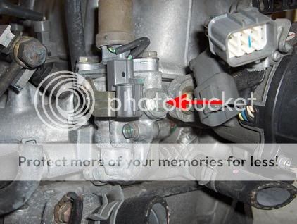 JDM VTEC solenoid
8. Advanced Diagnostic Techniques for ECU P2P VTEC
To ensure your ECU P2P VTEC system is running optimally, it’s essential to employ advanced diagnostic techniques. These methods go beyond basic troubleshooting and provide in-depth insights into the system’s performance.
8.1. Data Logging
Data logging involves recording engine parameters over time to analyze performance and identify potential issues. Use a data logging device to monitor parameters such as:
- Engine speed (RPM)
- Throttle position
- Air-fuel ratio
- Ignition timing
- VTEC solenoid activation
Analyze the data logs to identify any anomalies or deviations from the expected values.
8.2. Oscilloscope Testing
An oscilloscope is a powerful tool for analyzing electrical signals. Use an oscilloscope to test the signals from the ECU to the VTEC solenoid and pressure switch. This can help identify issues with the ECU’s output or wiring.
8.3. Fuel Trim Analysis
Fuel trims are adjustments made by the ECU to compensate for deviations in the air-fuel ratio. Analyze the short-term and long-term fuel trims to identify potential issues with the fuel system or sensors.
8.4. Compression Testing
Compression testing measures the compression in each cylinder. Low compression can indicate issues with the engine’s valves or piston rings, which can affect VTEC system performance.
8.5. Leak-Down Testing
Leak-down testing identifies leaks in the cylinders. This can help pinpoint issues with the valves, piston rings, or head gasket, which can affect engine performance and VTEC system operation.
Table 8: Advanced Diagnostic Techniques
| Technique | Description |
|---|---|
| Data Logging | Recording engine parameters over time to analyze performance and identify potential issues. |
| Oscilloscope Testing | Analyzing electrical signals to identify issues with the ECU’s output or wiring. |
| Fuel Trim Analysis | Analyzing fuel trims to identify potential issues with the fuel system or sensors. |
| Compression Testing | Measuring the compression in each cylinder to identify issues with the engine’s valves or piston rings. |
| Leak-Down Testing | Identifying leaks in the cylinders to pinpoint issues with the valves, piston rings, or head gasket, which can affect engine performance and VTEC system operation. |
9. How to Choose the Right Wiring Harness for Your ECU P2P VTEC
Selecting the correct wiring harness is crucial for a successful ECU P2P VTEC installation. A high-quality, compatible wiring harness ensures reliable connections and optimal performance.
9.1. Compatibility
Ensure the wiring harness is compatible with your specific vehicle model and ECU. Check the harness’s specifications to verify it’s designed for the ECU P2P VTEC system and your engine type (e.g., D16Y8).
9.2. Quality
Choose a wiring harness made from high-quality materials. Look for automotive-grade wiring, durable connectors, and robust construction. A well-built harness will withstand the harsh conditions in the engine bay and provide long-lasting performance.
9.3. Features
Consider the features of the wiring harness. Look for features such as:
- Pre-terminated connectors: These connectors simplify the installation process and ensure secure connections.
- Labeled wires: Labeled wires make it easier to identify each wire’s function, reducing the risk of errors.
- Heat shrink tubing: Heat shrink tubing provides insulation and protection for the wiring connections.
9.4. Brand Reputation
Choose a wiring harness from a reputable brand. Brands with a proven track record of quality and reliability are more likely to provide a harness that meets your needs.
9.5. Installation Instructions
Ensure the wiring harness comes with detailed installation instructions. Clear and concise instructions make the installation process easier and reduce the risk of errors.
Table 9: Factors to Consider When Choosing a Wiring Harness
| Factor | Description |
|---|---|
| Compatibility | Ensure the wiring harness is compatible with your specific vehicle model and ECU. |
| Quality | Choose a wiring harness made from high-quality materials, such as automotive-grade wiring and durable connectors. |
| Features | Consider features such as pre-terminated connectors, labeled wires, and heat shrink tubing. |
| Brand Reputation | Choose a wiring harness from a reputable brand with a proven track record of quality and reliability. |
| Installation Guide | Ensure the wiring harness comes with detailed installation instructions to simplify the installation process and reduce the risk of errors. |
10. ECU P2P VTEC: Frequently Asked Questions (FAQ)
Here are some frequently asked questions about the ECU P2P VTEC system:
-
What is the ECU P2P VTEC?
The ECU P2P VTEC is an Engine Control Unit (ECU) with the code P2P, used in Honda vehicles with VTEC engines, specifically the 1996-2000 Honda Civic EX with the D16Y8 engine.
-
How does the VTEC system work?
The VTEC system enhances engine performance by providing two different cam profiles: one for low-RPM efficiency and another for high-RPM power. The ECU activates a solenoid that allows oil pressure to engage a different set of rocker arms with a more aggressive cam profile at higher RPMs.
-
Why is proper wiring of the ECU P2P VTEC system essential?
Proper wiring is essential for optimal performance, engine safety, fuel efficiency, and reliability.
-
What are the common issues with incorrect wiring of the ECU P2P VTEC system?
Common issues include VTEC not engaging, erratic VTEC engagement, check engine light (CEL), and engine stalling.
-
How do I identify if I have a P2P ECU?
Locate the ECU under the passenger-side carpet or behind the kick panel and look for the “P2P” code on the ECU housing.
-
What tools are needed for wiring the ECU P2P VTEC system?
Essential tools include an OBD2 scanner, multimeter, wire strippers, crimping tool, soldering iron, heat gun, wiring harness, connectors, wire, heat shrink tubing, and electrical tape.
-
How do I troubleshoot a VTEC system that is not engaging?
Check wiring connections, test the VTEC solenoid’s functionality, verify adequate oil pressure, and ensure the ECU is properly configured for VTEC engagement.
-
What is ECU tuning and what are its benefits?
ECU tuning involves modifying the ECU’s programming to optimize engine performance. Benefits include increased horsepower, improved fuel economy, and better throttle response.
-
What is data logging and how is it used in diagnostics?
Data logging involves recording engine parameters over time to analyze performance and identify potential issues.
-
How can CAR-DIAGNOSTIC-TOOL.EDU.VN assist with ECU P2P VTEC wiring and diagnostics?
CAR-DIAGNOSTIC-TOOL.EDU.VN provides comprehensive diagnostic tools, detailed repair guides, remote support, technician training, a community forum, and quality products.
Ready to take your ECU P2P VTEC wiring and diagnostics to the next level? Contact CAR-DIAGNOSTIC-TOOL.EDU.VN today for expert advice, high-quality tools, and comprehensive training. Our team is here to help you achieve optimal engine performance and keep your Honda running smoothly. Don’t hesitate to reach out – we’re just a message or call away! Visit our website CAR-DIAGNOSTIC-TOOL.EDU.VN or contact us via Whatsapp at +1 (641) 206-8880. Our US support office is located at 1100 Congress Ave, Austin, TX 78701, United States.