The E69 Ecu Pinout is a critical piece of information for automotive technicians and garage owners because it provides a detailed map of the connections to the Engine Control Unit, essential for diagnostics, repair, and reprogramming. CAR-DIAGNOSTIC-TOOL.EDU.VN offers comprehensive guides, advanced diagnostic tools, and expert support to streamline your automotive repair processes, ensuring accuracy and efficiency. Enhance your expertise with our technician training programs and remote assistance for complex issues, available at CAR-DIAGNOSTIC-TOOL.EDU.VN.
Contents
- 1. Understanding the Basics of ECU Pinouts
- 2. Identifying the E69 ECU in GM Vehicles
- 3. Essential Tools for Working with ECU Pinouts
- 4. Step-by-Step Guide to Cloning an E69 ECU
- 5. Decoding the E69 ECU Pinout Diagram
- 6. Common Issues and Solutions Related to E69 ECU Pinouts
- 7. Advanced Diagnostic Techniques for E69 ECU Pinouts
- 8. Ensuring Safety When Working with E69 ECU Pinouts
- 9. The Future of ECU Diagnostics and Pinouts
- 10. Training and Resources for Mastering E69 ECU Pinouts
1. Understanding the Basics of ECU Pinouts
What exactly is an ECU pinout, and why is it so important in modern automotive diagnostics and repair? Let’s break it down.
An ECU (Engine Control Unit), often referred to as the car’s brain, controls various functions critical to the vehicle’s operation, from fuel injection and ignition timing to emissions control and overall engine performance. The ECU pinout is a detailed diagram that shows each pin on the ECU connector and what function it serves. This includes inputs such as sensor readings, outputs to control actuators, power supplies, and communication lines.
Why is it important?
- Accurate Diagnostics: The pinout allows technicians to accurately test signals to and from the ECU, which helps in pinpointing whether a problem lies within the ECU itself, the wiring, or the sensors and actuators connected to it.
- Efficient Repairs: Having a reliable E69 ECU pinout can significantly reduce diagnostic time, enabling technicians to quickly identify and fix issues.
- Safe Reprogramming: When reprogramming or remapping an ECU, the pinout ensures that connections are made correctly, avoiding potential damage to the ECU or other vehicle systems.
- Customization and Upgrades: For those looking to modify or upgrade their vehicle’s performance, understanding the pinout is crucial for correctly interfacing with the ECU.
 Obdstar Dc706 Clone Gm E69 Ecm 0
2. Identifying the E69 ECU in GM Vehicles
How can you identify the E69 ECU, and in which GM vehicles is it typically found? Correct identification is essential for accurate diagnostics and repairs.
The E69 ECU is a specific type of engine control unit used in various General Motors (GM) vehicles. Identifying it correctly is crucial before attempting any diagnostic, repair, or reprogramming work.
Identifying the E69 ECU:
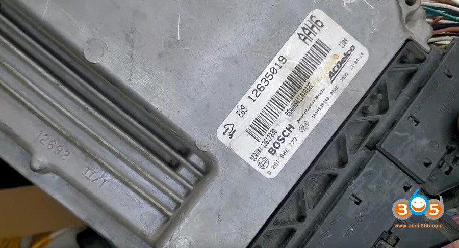
- Physical Inspection: The E69 ECU typically has a label on its housing that clearly indicates the model number. Look for this label, usually found on the top or side of the unit.
- Vehicle Documentation: Check the vehicle’s service manual or repair documentation. These resources often provide detailed information about the ECU model used in that specific vehicle.
- Diagnostic Tools: Use a diagnostic tool like the OBDSTAR DC706 available at CAR-DIAGNOSTIC-TOOL.EDU.VN to read the ECU identification information directly from the vehicle’s computer system. This tool can quickly identify the ECU model and provide other relevant data.
Common GM Vehicles Using the E69 ECU:
The E69 ECU is commonly found in several GM vehicles, including:
- Chevrolet Cruze
- Chevrolet Sonic
- Buick Encore
- Other models within the 2011-2016 range using similar engine configurations
Why Proper Identification Matters:
- Pinout Accuracy: Different ECUs have different pinouts. Using the wrong pinout can lead to incorrect connections, potentially damaging the ECU or vehicle.
- Diagnostic Compatibility: Diagnostic tools and software are ECU-specific. Identifying the correct ECU ensures that you use the appropriate tools and procedures.
- Component Compatibility: When replacing or upgrading ECU components, it’s vital to ensure that the new parts are compatible with the specific ECU model.
3. Essential Tools for Working with ECU Pinouts
What tools are essential when working with ECU pinouts, and how do they help ensure accuracy and safety during diagnostics and repairs?
Working with ECU pinouts requires a combination of specialized tools to ensure accuracy, safety, and efficiency. Here’s a list of essential tools that technicians should have on hand:
- Multimeter:
- Purpose: Used to measure voltage, current, and resistance. Essential for verifying the electrical integrity of circuits and components connected to the ECU.
- Features: Look for a digital multimeter with high accuracy and features like auto-ranging and continuity testing.
- Oscilloscope:
- Purpose: Allows you to visualize electrical signals over time. Crucial for diagnosing intermittent issues and analyzing signal patterns from sensors and actuators.
- Features: A two-channel oscilloscope is generally sufficient for most automotive applications.
- Breakout Box:
- Purpose: Provides a safe and convenient way to access the pins of the ECU without damaging the connector or wiring.
- Features: Choose a breakout box specifically designed for the E69 ECU to ensure compatibility.
- Diagnostic Scan Tool:
- Purpose: Reads diagnostic trouble codes (DTCs), displays live data, and performs ECU reprogramming.
- Features: The OBDSTAR DC706 from CAR-DIAGNOSTIC-TOOL.EDU.VN is an excellent choice, offering comprehensive diagnostic and cloning capabilities.
- Wiring Diagrams and Pinout Charts:
- Purpose: Provides detailed information about the ECU pinout and wiring connections.
- Features: Ensure you have the correct wiring diagrams for the specific vehicle and ECU model.
- Power Supply:
- Purpose: Supplies stable and regulated power to the ECU during testing and reprogramming.
- Features: A variable power supply is ideal, allowing you to adjust the voltage as needed.
- Logic Probe:
- Purpose: Quickly checks the logic state (high or low) of digital signals.
- Features: Look for a logic probe with LED indicators for easy visual confirmation.
- Test Leads and Connectors:
- Purpose: Used to make secure and reliable connections to the ECU pins.
- Features: Invest in a variety of test leads, including back probes, alligator clips, and piercing probes.
- Anti-Static Wrist Strap:
- Purpose: Prevents electrostatic discharge (ESD) from damaging the ECU.
- Features: Essential when handling the ECU directly.
- Software and Programming Tools:
- Purpose: Allows you to reprogram or remap the ECU.
- Features: Ensure that you have the correct software and programming tools for the E69 ECU.
By having these tools, you can accurately diagnose issues, perform necessary repairs, and safely reprogram the ECU, ensuring optimal vehicle performance. Remember to always consult the vehicle’s service manual and follow proper safety procedures when working with ECU pinouts and electrical systems.
4. Step-by-Step Guide to Cloning an E69 ECU
Can you provide a step-by-step guide on how to clone an E69 ECU using tools like the OBDSTAR DC706, MP001 programmer, and P003+ adapter?
Cloning an ECU involves creating an exact copy of the data from one ECU (the original) to another (the donor). This is useful when replacing a faulty ECU, as it avoids the need to reprogram the new ECU with vehicle-specific data. Here’s a detailed step-by-step guide on how to clone an E69 ECU using the OBDSTAR DC706, MP001 programmer, and P003+ adapter, with additional tips for troubleshooting and ensuring a smooth process.
Required Tools and Equipment:
- OBDSTAR DC706 (available here)
- OBDSTAR MP001 programmer (available here)
- OBDSTAR P003+ adapter (available here)
- E69 ECU (original and donor)
- Power supply
- Wiring and connectors as per the pinout diagram
- Computer with OBDSTAR software installed
Step-by-Step Guide:
-
Preparation:
- Ensure that both the original and donor ECUs are compatible with the vehicle.
- Connect the OBDSTAR DC706 to a stable power source.
- Install the OBDSTAR software on your computer and ensure it is up-to-date.
-
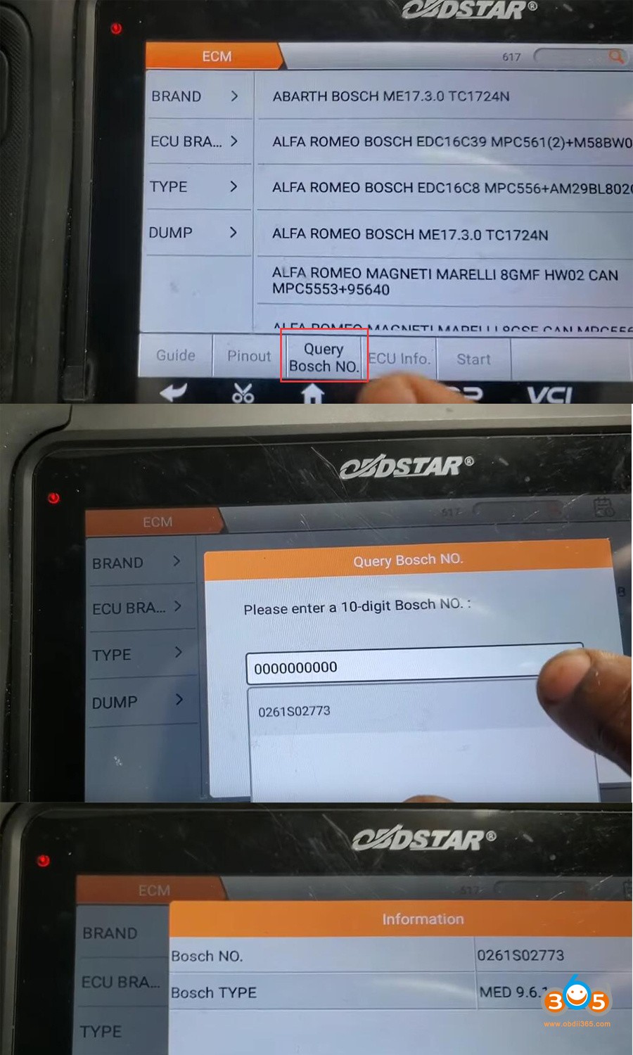
Identify the ECU:
- In the DC706 software, navigate to the ECU Flasher section.
- Select the car brand (e.g., Chevrolet) and search for the MED9.6.1 ECU type, commonly associated with the E69.
- Verify that the selected ECU matches the E69 ECU you are working with.
-
Connect the Equipment:
- Follow the wiring diagram provided by OBDSTAR for the E69 ECU. This diagram will show you how to connect the DC706, MP001, and P003+ to the ECU.
- Connect the MP001 and P003+ to the DC706.
- Connect the DC706, MP001, and P003+ to the E69 ECU on the bench.
-
Read the Original ECU Data:
- In the DC706 software, select the option to read the ECU data.
- Choose to read both the EXT EEPROM and EXT Flash. These contain the critical data needed for cloning.
- Save the data files to your computer. It’s a good practice to create a folder specifically for this ECU to keep the files organized.
-
Prepare the Donor ECU:
- Disconnect the original ECU and connect the donor ECU to the DC706, MP001, and P003+ using the same wiring setup.
-
Write Data to the Donor ECU:
- In the DC706 software, select the option to write to the ECU.
- First, write the EXT Flash file that you saved from the original ECU.
- After the flash writing is complete, write the EXT EEPROM file.
-
Verify the Cloning:
- After writing both the flash and EEPROM data, it’s crucial to verify that the cloning process was successful.
- Read the EXT EEPROM from the donor ECU and compare it to the original EEPROM file using a hex editor.
- Ensure that the VIN and other critical data match between the original and cloned ECUs.
-
Install the Cloned ECU:
- Disconnect the donor ECU from the cloning setup.
- Install the cloned ECU in the vehicle.
- Start the vehicle to ensure that it runs correctly with the cloned ECU.
 Obdstar Dc706 Clone Gm E69 Ecm 5
5. Decoding the E69 ECU Pinout Diagram
How do you decode an E69 ECU pinout diagram, and what key information can be extracted from it for effective troubleshooting?
An ECU pinout diagram is a detailed map of the connections to the Engine Control Unit (ECU), providing critical information for diagnosing and repairing automotive electronic systems. Decoding this diagram accurately is essential for effective troubleshooting. Here’s a guide to help you understand and use an E69 ECU pinout diagram:
-
Understanding the Basics:
- Pin Numbers: Each pin on the ECU connector is assigned a unique number. The pinout diagram will typically label each pin with its corresponding number.
- Wire Colors: The diagram often indicates the color of the wire connected to each pin. This helps in identifying the correct wire when working on the vehicle.
- Signal Descriptions: Each pin is associated with a specific function or signal. The diagram will describe what each pin is used for (e.g., sensor input, actuator output, power supply, ground).
- Voltage Levels: Some diagrams may provide information about the expected voltage levels at each pin under different operating conditions.
-
Key Components of the Pinout Diagram:
- Connector Views: The diagram usually includes a connector view, showing the physical layout of the pins. This helps in orienting the connector correctly.
- Wiring Schematics: The pinout diagram is often part of a larger wiring schematic that shows how the ECU connects to various sensors, actuators, and other components in the vehicle.
- Ground Points: Identifying ground points is crucial for troubleshooting electrical issues. The diagram will show which pins are connected to ground.
- Power Supply Pins: These pins provide power to the ECU. The diagram will indicate the voltage requirements (e.g., 12V, 5V) and the source of the power supply.
- Input Pins: These pins receive signals from sensors and other devices. The diagram will describe the type of signal (e.g., analog, digital) and the expected voltage range.
- Output Pins: These pins send signals to control actuators, relays, and other components. The diagram will describe the type of signal and the components being controlled.
-
Using the Pinout Diagram for Troubleshooting:
- Identify the Problem: Start by identifying the symptoms or trouble codes that indicate a problem with the ECU or its connected components.
- Locate the Relevant Pins: Use the pinout diagram to locate the pins associated with the affected components or circuits.
- Measure Voltage and Resistance: Use a multimeter to measure the voltage and resistance at the relevant pins. Compare your measurements to the expected values listed in the diagram or service manual.
- Check for Continuity: Use a multimeter to check for continuity between the ECU pins and the connected components. This helps in identifying broken or shorted wires.
- Inspect Connectors and Wiring: Visually inspect the ECU connector and wiring for any signs of damage, corrosion, or loose connections.
-
Example Scenario:
- Problem: The engine is misfiring, and the diagnostic tool shows a trouble code related to the fuel injector on cylinder 1.
- Using the Pinout Diagram:
- Locate the pinout diagram for the E69 ECU in the vehicle’s service manual.
- Identify the pin on the ECU that controls the fuel injector for cylinder 1.
- Use a multimeter to measure the voltage at that pin while the engine is running.
- Compare the measured voltage to the expected value. If the voltage is incorrect, there may be a problem with the ECU, the wiring, or the fuel injector itself.
- Check the continuity between the ECU pin and the fuel injector connector to rule out any broken wires.
-
Tips for Effective Decoding:
- Use High-Quality Diagrams: Always use high-quality, accurate pinout diagrams from reliable sources.
- Cross-Reference Information: Cross-reference the pinout diagram with other service information, such as wiring schematics and component locations.
- Take Your Time: Decoding a pinout diagram can be complex, so take your time and double-check your work.
- Use Diagnostic Tools: Use diagnostic tools like the OBDSTAR DC706 from CAR-DIAGNOSTIC-TOOL.EDU.VN to read live data and perform tests that can help in identifying the problem.
By following these steps, you can effectively decode an E69 ECU pinout diagram and use it to troubleshoot automotive electronic systems efficiently.
6. Common Issues and Solutions Related to E69 ECU Pinouts
What are some common issues related to E69 ECU pinouts, and what troubleshooting steps can be taken to resolve them effectively?
Working with ECU pinouts can sometimes present challenges. Here are some common issues related to E69 ECU pinouts, along with troubleshooting steps to resolve them effectively:
-
Corrosion and Damaged Connectors:
-
Issue: Corrosion can build up on the pins and connectors due to moisture and environmental factors, leading to poor electrical connections. Physical damage to connectors can also cause similar issues.
-
Symptoms: Intermittent electrical problems, such as sensors not reading correctly, actuators not functioning, or the ECU not communicating with diagnostic tools.
-
Troubleshooting Steps:
- Visual Inspection: Carefully inspect the ECU connector and pins for any signs of corrosion, damage, or loose connections.
- Cleaning: Use a specialized electrical contact cleaner to clean the pins and connectors. Ensure the cleaner is safe for use on automotive electronics.
- Repair or Replacement: If the connector or pins are severely damaged, they may need to be repaired or replaced. Connector repair kits are available for many vehicles.
-
-
Wiring Problems:
-
Issue: Wires connected to the ECU pins can become damaged due to chafing, heat, or age. This can lead to open circuits, short circuits, or high resistance.
-
Symptoms: Similar to corrosion, wiring problems can cause intermittent electrical issues, sensor malfunctions, and ECU communication errors.
-
Troubleshooting Steps:
- Continuity Testing: Use a multimeter to perform continuity tests on the wires connected to the ECU pins. Check for open circuits (no continuity) or short circuits (continuity to ground when there shouldn’t be).
- Voltage Drop Testing: Perform voltage drop tests to identify wires with high resistance. Excessive voltage drop can indicate a corroded or damaged wire.
- Visual Inspection: Inspect the wiring harness for any signs of damage, such as cuts, abrasions, or melted insulation.
- Repair or Replacement: Repair any damaged wires by splicing in new sections of wire and using heat-shrink tubing to protect the connections. If the wiring harness is severely damaged, it may need to be replaced.
-
-
Incorrect Pinout Information:
-
Issue: Using incorrect or outdated pinout information can lead to misdiagnoses and incorrect repairs.
-
Symptoms: Inaccurate voltage readings, incorrect component activation, and potential damage to the ECU or other vehicle systems.
-
Troubleshooting Steps:
- Verify Pinout Information: Always verify that you are using the correct pinout information for the specific vehicle and ECU model. Consult multiple sources, such as the vehicle’s service manual, online databases, and diagnostic tool software.
- Cross-Reference Information: Cross-reference the pinout information with wiring schematics and component locations to ensure accuracy.
- Use Known Good Data: Compare your readings and test results to known good data from a functioning vehicle or a reliable source.
-
-
Grounding Issues:
-
Issue: Poor grounding can cause a variety of electrical problems, including sensor malfunctions, ECU communication errors, and intermittent performance issues.
-
Symptoms: Erratic sensor readings, engine misfires, and the ECU not communicating with diagnostic tools.
-
Troubleshooting Steps:
- Check Ground Connections: Inspect all ground connections associated with the ECU and its connected components. Ensure that the connections are clean, tight, and free from corrosion.
- Measure Ground Resistance: Use a multimeter to measure the resistance between the ECU ground pins and the vehicle’s chassis. The resistance should be very low (close to 0 ohms).
- Add Additional Ground Wires: If necessary, add additional ground wires to improve the grounding of the ECU and its connected components.
-
-
Software and Programming Issues:
-
Issue: Problems with the ECU’s software or programming can cause a variety of performance issues, including engine misfires, poor fuel economy, and the ECU not functioning correctly.
-
Symptoms: Engine running poorly, diagnostic trouble codes (DTCs), and the ECU not communicating with diagnostic tools.
-
Troubleshooting Steps:
- Check for Software Updates: Use a diagnostic tool like the OBDSTAR DC706 from CAR-DIAGNOSTIC-TOOL.EDU.VN to check for any available software updates for the ECU.
- Reprogram the ECU: If necessary, reprogram the ECU with the latest software version. Follow the manufacturer’s instructions carefully to avoid damaging the ECU.
- Verify Programming: After reprogramming the ECU, verify that the programming was successful by checking for any error messages or trouble codes.
-
By following these troubleshooting steps, you can effectively diagnose and resolve common issues related to E69 ECU pinouts, ensuring optimal vehicle performance and reliability.
 Obdstar Dc706 Clone Gm E69 Ecm 2
7. Advanced Diagnostic Techniques for E69 ECU Pinouts
What advanced diagnostic techniques can be employed when working with E69 ECU pinouts to tackle complex or intermittent issues?
When dealing with complex or intermittent issues related to E69 ECU pinouts, advanced diagnostic techniques can provide more insight than basic troubleshooting methods. These techniques often involve specialized equipment and a deeper understanding of automotive electronics. Here are some advanced diagnostic techniques to employ:
-
Oscilloscope Diagnostics:
- Technique: Using an oscilloscope to analyze the waveform patterns of signals at the ECU pins.
- How it Helps: An oscilloscope can reveal signal abnormalities that a multimeter might miss, such as signal noise, dropouts, or incorrect signal timing.
- Application:
- Sensor Signals: Verify the integrity of sensor signals (e.g., crankshaft position sensor, camshaft position sensor) by examining their waveforms.
- Actuator Control Signals: Analyze the control signals sent to actuators (e.g., fuel injectors, ignition coils) to ensure they are within the correct parameters.
- Communication Signals: Diagnose communication issues on CAN bus or other communication networks by examining the signal waveforms.
-
CAN Bus Diagnostics:
- Technique: Using a CAN bus analyzer or diagnostic tool to monitor and analyze the data traffic on the vehicle’s CAN bus network.
- How it Helps: CAN bus diagnostics can identify communication issues between the ECU and other modules in the vehicle, such as the transmission control module (TCM), anti-lock braking system (ABS), and body control module (BCM).
- Application:
- Communication Errors: Identify communication errors or missing messages on the CAN bus.
- Data Analysis: Analyze the data being transmitted on the CAN bus to diagnose performance issues or sensor malfunctions.
- Module Identification: Identify which modules are communicating on the CAN bus and verify their functionality.
-
Load Testing:
- Technique: Applying a load to a circuit and measuring the voltage drop to identify wiring or component issues.
- How it Helps: Load testing can reveal wiring problems that might not be apparent with a simple continuity test, such as high resistance due to corrosion or damaged wires.
- Application:
- Power Circuits: Test the power supply circuits to the ECU by applying a load and measuring the voltage drop.
- Ground Circuits: Test the ground circuits by applying a load and measuring the voltage drop.
- Actuator Circuits: Test the circuits for actuators (e.g., fuel injectors, solenoids) by applying a load and measuring the voltage drop.
-
Signal Injection:
- Technique: Injecting a known signal into a circuit to test the functionality of the ECU and its connected components.
- How it Helps: Signal injection can help isolate problems by bypassing certain components or circuits.
- Application:
- Sensor Simulation: Simulate sensor signals to test the ECU’s response.
- Actuator Activation: Directly activate actuators to verify their functionality.
- Circuit Testing: Test the integrity of wiring and connectors by injecting a signal and measuring the output.
-
Data Logging and Analysis:
- Technique: Recording live data from the ECU over a period of time and analyzing the data to identify patterns or anomalies.
- How it Helps: Data logging can reveal intermittent issues or performance problems that might not be apparent during a static test.
- Application:
- Performance Monitoring: Monitor engine performance parameters (e.g., RPM, fuel pressure, ignition timing) to identify issues.
- Sensor Analysis: Analyze sensor data to identify malfunctions or inconsistencies.
- Event Recording: Record data during specific events (e.g., acceleration, deceleration) to diagnose performance problems.
-
Environmental Testing:
- Technique: Testing the ECU and its connected components under different environmental conditions (e.g., temperature, vibration) to identify issues that only occur under certain circumstances.
- How it Helps: Environmental testing can reveal intermittent problems that are caused by temperature changes, vibration, or other environmental factors.
- Application:
- Temperature Testing: Heat or cool the ECU and its connected components to see if any issues arise.
- Vibration Testing: Vibrate the ECU and its connected components to simulate the effects of driving on a rough road.
- Humidity Testing: Expose the ECU and its connected components to high humidity to see if any corrosion-related issues occur.
By employing these advanced diagnostic techniques, you can effectively tackle complex or intermittent issues related to E69 ECU pinouts and ensure optimal vehicle performance.
8. Ensuring Safety When Working with E69 ECU Pinouts
What safety precautions should be followed when working with E69 ECU pinouts to protect both the technician and the vehicle’s electronic systems?
Working with automotive electronics, especially ECU pinouts, requires strict adherence to safety protocols to protect both the technician and the vehicle’s systems. Here are essential safety precautions to follow when working with E69 ECU pinouts:
-
Disconnect the Battery:
- Precaution: Always disconnect the vehicle’s battery before working on the ECU or any electrical components.
- Reason: Disconnecting the battery prevents accidental short circuits and electrical shocks, which can damage the ECU or injure the technician.
- Procedure: Disconnect the negative terminal first, followed by the positive terminal.
-
Use Proper Grounding Techniques:
- Precaution: Use proper grounding techniques to prevent electrostatic discharge (ESD) from damaging the ECU.
- Reason: ECUs are sensitive to ESD, which can occur when handling electronic components.
- Procedure: Wear an anti-static wrist strap connected to a grounded surface. Use an anti-static mat on your work area.
-
Avoid Working in Wet Conditions:
- Precaution: Do not work on the ECU or electrical systems in wet or damp conditions.
- Reason: Water can cause short circuits and electrical shocks, which can damage the ECU or injure the technician.
- Procedure: Ensure the work area is dry and well-ventilated.
-
Use Insulated Tools:
- Precaution: Use insulated tools when working on electrical systems.
- Reason: Insulated tools provide protection against electrical shocks.
- Procedure: Use screwdrivers, pliers, and other tools with insulated handles.
-
Follow the Correct Wiring Diagrams:
- Precaution: Always use the correct wiring diagrams and pinout information for the specific vehicle and ECU model.
- Reason: Incorrect wiring can damage the ECU or other vehicle systems.
- Procedure: Verify that the wiring diagrams and pinout information are accurate and up-to-date. Cross-reference the information with multiple sources if necessary.
-
Avoid Applying Excessive Force:
- Precaution: Avoid applying excessive force when connecting or disconnecting connectors from the ECU.
- Reason: Excessive force can damage the connectors or the ECU pins.
- Procedure: Use gentle, steady pressure when connecting or disconnecting connectors. Ensure the connectors are properly aligned before applying force.
-
Protect the ECU from Physical Damage:
- Precaution: Protect the ECU from physical damage, such as dropping it or exposing it to extreme temperatures.
- Reason: Physical damage can impair the ECU’s functionality.
- Procedure: Handle the ECU carefully and store it in a safe place when not in use.
-
Use Proper Ventilation:
- Precaution: Use proper ventilation when working with solvents, cleaners, or other chemicals.
- Reason: Some chemicals can be harmful if inhaled.
- Procedure: Work in a well-ventilated area or use a respirator when necessary.
-
Double-Check Connections:
- Precaution: Double-check all connections before reconnecting the battery or powering up the ECU.
- Reason: Incorrect connections can damage the ECU or other vehicle systems.
- Procedure: Verify that all connectors are properly seated and that the wiring is correct.
-
Consult the Service Manual:
- Precaution: Always consult the vehicle’s service manual for specific safety instructions and procedures.
- Reason: The service manual provides detailed information about the vehicle’s electrical systems and the proper procedures for working on them.
- Procedure: Read and understand the relevant sections of the service manual before beginning any work on the ECU.
By following these safety precautions, you can protect yourself and the vehicle’s electronic systems when working with E69 ECU pinouts.
9. The Future of ECU Diagnostics and Pinouts
How are ECU diagnostics and pinout technology evolving, and what future advancements can technicians anticipate in this field?
The field of ECU diagnostics and pinout technology is continually evolving, driven by advancements in automotive technology, increasing complexity of vehicle systems, and the need for more efficient and accurate diagnostic methods. Here are some future advancements that technicians can anticipate in this field:
-
Enhanced Diagnostic Tools:
- Advancement: Diagnostic tools will become more powerful and versatile, with enhanced capabilities for ECU diagnostics, programming, and data analysis.
- Features:
- Advanced Diagnostics: Diagnostic tools will offer more advanced diagnostic functions, such as automated fault detection, guided troubleshooting, and predictive maintenance.
- Wireless Connectivity: Wireless connectivity will become more prevalent, allowing technicians to access diagnostic information and perform ECU programming remotely.
- Cloud-Based Diagnostics: Cloud-based diagnostic platforms will provide access to real-time data, diagnostic resources, and remote expert support.
-
Improved Pinout Information:
- Advancement: Pinout information will become more accurate, comprehensive, and easily accessible.
- Features:
- Interactive Pinout Diagrams: Interactive pinout diagrams will allow technicians to zoom in on specific pins, view detailed information about each pin, and access related wiring schematics.
- Real-Time Data Integration: Pinout information will be integrated with real-time data from the ECU, allowing technicians to monitor signal values and identify issues more efficiently.
- Mobile Apps: Mobile apps will provide technicians with access to pinout information and diagnostic resources on their smartphones or tablets.
-
Artificial Intelligence (AI) and Machine Learning (ML):
- Advancement: AI and ML technologies will be integrated into diagnostic tools to provide more intelligent and automated diagnostic capabilities.
- Features:
- Automated Fault Diagnosis: AI-powered diagnostic tools will be able to automatically diagnose faults based on diagnostic trouble codes (DTCs), sensor data, and other information.
- Predictive Maintenance: ML algorithms will analyze vehicle data to predict potential maintenance issues before they occur, allowing technicians to proactively address problems.
- Personalized Recommendations: AI-powered diagnostic tools will provide personalized recommendations for repairs and maintenance based on the vehicle’s history and driving conditions.
-
Augmented Reality (AR) and Virtual Reality (VR):
- Advancement: AR and VR technologies will be used to enhance the diagnostic and repair process, providing technicians with immersive and interactive experiences.
- Features:
- AR-Guided Diagnostics: AR overlays will provide technicians with step-by-step instructions for diagnosing and repairing ECU issues, overlaying the instructions onto the vehicle in real-time.
- VR Training: VR simulations will allow technicians to practice diagnosing and repairing ECU issues in a safe and controlled environment.
- Remote Collaboration: AR and VR technologies will enable remote collaboration between technicians, allowing experts to provide guidance and support from anywhere in the world.
-
Standardization and Interoperability:
- Advancement: Efforts to standardize diagnostic protocols and data formats will improve interoperability between diagnostic tools and vehicle systems.
- Features:
- Open Diagnostic Standards: Open diagnostic standards will allow diagnostic tools from different manufacturers to communicate with vehicle systems using a common language.
- Data Sharing: Standardized data formats will facilitate data sharing between diagnostic tools, vehicle manufacturers, and other stakeholders.
- Remote Diagnostics: Standardized diagnostic protocols will enable remote diagnostics and over-the-air (OTA) updates for ECUs.
By embracing these future advancements, technicians can enhance their diagnostic skills, improve their efficiency, and stay ahead of the curve in the rapidly evolving field of automotive electronics. CAR-DIAGNOSTIC-TOOL.EDU.VN is committed to providing technicians with the tools, resources, and training they need to succeed in this dynamic industry.
10. Training and Resources for Mastering E69 ECU Pinouts
What training programs and resources are available to help automotive technicians master E69 ECU pinouts and related diagnostic skills?
Mastering E69 ECU pinouts and related diagnostic skills requires a combination of theoretical knowledge, practical experience, and access to reliable resources. Here are several training programs and resources available to help automotive technicians develop these skills:
-
Automotive Technical Schools and Colleges:
- Programs: Many technical schools and colleges offer automotive technology programs that cover ECU diagnostics, wiring diagrams, and electrical troubleshooting.
- Curriculum: These programs typically include classroom instruction, hands-on training, and practical exercises.
- Benefits: Students gain a solid foundation in automotive electronics and develop the skills needed to diagnose and repair complex electrical issues.
-
Online Training Courses:
- Platforms: Online training platforms, such as Udemy, Coursera, and Skillshare, offer a variety of courses on ECU diagnostics, wiring diagrams, and electrical troubleshooting.
- Content: These courses typically include video lectures, quizzes, and hands-on exercises.
- Benefits: Technicians can learn at their own pace and access a wide range of training materials from anywhere in the world.
-
Manufacturer-Specific Training:
- Programs: Vehicle manufacturers, such as General Motors (GM), offer training programs for technicians who work on their vehicles.
- Content: These programs cover the specific ECUs and electrical systems used in the manufacturer’s vehicles, including the E69 ECU.
- Benefits: Technicians gain in-depth knowledge of the manufacturer’s vehicles and learn how to diagnose and repair them effectively.
-
Industry Certifications:
- Certifications: Industry certifications, such as those offered by the National Institute for Automotive Service Excellence (ASE), demonstrate