The Obd2 Scanner Connector is your gateway to understanding and resolving vehicle issues. At CAR-DIAGNOSTIC-TOOL.EDU.VN, we provide comprehensive solutions including advanced diagnostic tools, detailed repair guides, and expert technical support, ensuring you can accurately diagnose and efficiently repair any vehicle. We also offer hands-on technician training and remote support to ensure you’re never alone in tackling complex diagnostic challenges.
Contents
- 1. Understanding the OBD2 System
- 1.1. What is OBD2?
- 1.2. OBD2 History and Evolution
- 1.3. Future Trends in OBD
- 2. The OBD2 Connector: Your Car’s Diagnostic Port
- 2.1. What is the OBD2 Connector?
- 2.2. OBD2 Connector Types: A vs. B
- 2.3. Finding the OBD2 Connector in Your Car
- 3. OBD2 Protocols and Communication
- 3.1. OBD2 and CAN Bus (ISO 15765-4)
- 3.2. OBD2 CAN Identifiers
- 3.3. OBD2 vs. Proprietary CAN Protocols
- 3.4. Other OBD2 Protocols
- 4. Understanding OBD2 Messages
- 4.1. ISO-TP (ISO 15765-2): Transporting OBD2 Messages
- 4.2. Structure of an OBD2 Diagnostic Message
- 4.3. OBD2 Modes (Services)
- 4.4. OBD2 Parameter IDs (PIDs)
- 4.5. Practical Example: Requesting Vehicle Speed
- 5. How to Use an OBD2 Scanner
- 5.1. Connecting the OBD2 Scanner
- 5.2. Reading Diagnostic Trouble Codes (DTCs)
- 5.3. Interpreting OBD2 Data
- 5.4. Clearing Codes and Monitoring
- 6. Logging and Decoding OBD2 Data
- 6.1. Step-by-Step Guide to Logging OBD2 Data
- 6.2. Tools for Logging OBD2 Data
- 6.3. Understanding OBD2 PID Requests and Responses
- 7. Advanced OBD2 Functions and Techniques
- 7.1. Multi-Frame Communication (ISO-TP)
- 7.2. Extracting the Vehicle Identification Number (VIN)
- 7.3. Requesting Multiple PIDs
- 7.4. Reading Diagnostic Trouble Codes (DTCs) with Mode 0x03
- 8. Real-World Applications of OBD2 Data
- 8.1. Use Cases for OBD2 Data Logging
- 8.2. Applications in Automotive Repair
- 8.3. Fleet Management
- 9. Choosing the Right OBD2 Scanner
- 9.1. Types of OBD2 Scanners
- 9.2. Key Features to Look For
- 9.3. Top OBD2 Scanner Brands
- 10. Common OBD2 Problems and Solutions
- 10.1. Troubleshooting OBD2 Scanner Connection Issues
- 10.2. Dealing with Incorrect Code Readings
- 10.3. Addressing Software and Hardware Glitches
- FAQ: Your Questions About OBD2 Answered
- Q1: What is the main purpose of the OBD2 system?
- Q2: Where is the OBD2 connector located in my car?
- Q3: How do I read and interpret OBD2 codes?
- Q4: What should I do after reading a DTC?
- Q5: Can I clear OBD2 codes without fixing the problem?
- Q6: What is the difference between a basic OBD2 scanner and a professional scanner?
- Q7: How often should I scan my car with an OBD2 scanner?
- Q8: Can OBD2 scanners be used on all cars?
- Q9: What is live data and why is it important?
- Q10: Are there any risks associated with using an OBD2 scanner?
- Take Action Today
1. Understanding the OBD2 System
OBD2 (On-Board Diagnostics II) is a standardized system that provides access to a vehicle’s self-diagnostic data. Required in most vehicles since 1996, it helps mechanics and vehicle owners diagnose issues by providing trouble codes and real-time data.
1.1. What is OBD2?
OBD2 is a vehicle’s built-in self-diagnostic system. It is a standardized protocol that allows extraction of diagnostic trouble codes (DTCs) and real-time data via the OBD2 connector. Ever noticed the malfunction indicator light on your dashboard? That is your car telling you there is an issue. If you visit a mechanic, he will use an OBD2 scanner to diagnose the issue. The tool sends ‘OBD2 requests’ to the car and the car responds with ‘OBD2 responses’ that can contain e.g. speed, fuel level or Diagnostic Trouble Codes (DTCs) – making it possible to troubleshoot issues faster.
According to SAE International, the OBD2 standard was recommended by the Society of Automotive Engineers (SAE) and standardized DTCs and the OBD connector across manufacturers (SAE J1962).
1.2. OBD2 History and Evolution
Originating in California, the California Air Resources Board (CARB) mandated OBD in all new cars from 1991 for emission control. The OBD2 standard was recommended by the Society of Automotive Engineers (SAE) and standardized DTCs and the OBD connector across manufacturers (SAE J1962).
From there, the OBD2 standard was rolled out step-by-step:
- 1996: OBD2 made mandatory in USA for cars/light trucks
- 2001: Required in EU for gasoline cars
- 2003: Required in EU also for diesel cars (EOBD)
- 2005: OBD2 was required in US for medium duty vehicles
- 2008: US cars must use ISO 15765-4 (CAN) as OBD2 basis
- 2010: Finally, OBD2 was required in US heavy duty vehicles
1.3. Future Trends in OBD
OBD2 is evolving. According to a report by McKinsey, connected car technologies, including advanced OBD systems, are expected to generate up to $750 billion in new revenue streams by 2030. Key trends include:
- WWH-OBD (World Wide Harmonized OBD) and OBDonUDS (OBD on UDS): Streamlining and enhancing OBD communication by leveraging the UDS protocol as basis.
- OBD3: Adding telematics for remote emission control checks.
- Data Access Restrictions: Manufacturers potentially limiting third-party access to OBD2 data for security and commercial reasons.
2. The OBD2 Connector: Your Car’s Diagnostic Port
The OBD2 connector, a 16-pin port, is the physical interface used to access your vehicle’s diagnostic data. It’s standardized, but its location can vary.
2.1. What is the OBD2 Connector?
The 16-pin OBD2 connector lets you access data from your car easily and is specified in the standard SAE J1962 / ISO 15031-3. The connector is near your steering wheel, but may be hidden. Pin 16 supplies battery power (often while the ignition is off). The OBD2 pinout depends on the communication protocol. The most common lower-layer protocol is CAN bus, meaning that pins 6 (CAN-H) and 14 (CAN-L) will typically be connected.
2.2. OBD2 Connector Types: A vs. B
You may encounter both type A and type B OBD2 connectors. Type A is typically found in cars, while type B is common in medium and heavy-duty vehicles.
- Type A: 12V power supply
- Type B: 24V power supply
Note that the type B OBD2 connector has an interrupted groove in the middle. As a result, a type B OBD2 adapter cable will be compatible with both types A and B, while a type A will not fit into a type B socket.
2.3. Finding the OBD2 Connector in Your Car
The OBD2 connector is typically located within 2 feet of the steering wheel, but can be hidden. Common locations include:
- Under the dashboard on the driver’s side
- Inside the center console
- Behind an ashtray or panel
3. OBD2 Protocols and Communication
OBD2 communication relies on several protocols to transmit data. CAN (Controller Area Network) bus is the most common since 2008, but older vehicles may use other protocols.
3.1. OBD2 and CAN Bus (ISO 15765-4)
Since 2008, CAN bus has been the mandatory lower-layer protocol for OBD2 in all cars sold in the US as per ISO 15765.
ISO 15765-4 (aka Diagnostics over CAN or DoCAN) refers to a set of restrictions applied to the CAN standard (ISO 11898).
Specifically, it standardizes the CAN interface for test equipment with focus on the physical, data link and network layer:
- The CAN bus bit-rate must be either 250K or 500K
- The CAN IDs can be 11-bit or 29-bit
- Specific CAN IDs are used for OBD requests/responses
- The diagnostic CAN frame data length must be 8 bytes
- The OBD2 adapter cable must be max 5 meters
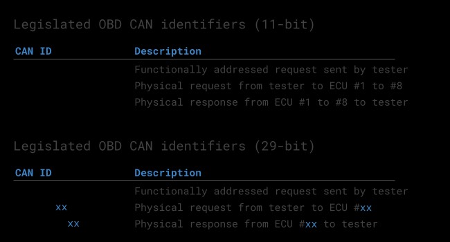
3.2. OBD2 CAN Identifiers
All OBD2 communication involves request / response messages. In most cars, 11-bit CAN IDs are used for OBD2 communication.
Here, the ‘Functional Addressing’ ID is 0x7DF, which corresponds to asking all OBD2 compatible ECUs if they have data to report on the requested parameter (see ISO 15765-4). In contrast, CAN IDs 0x7E0-0x7E7 can be used to perform ‘Physical Addressing’ requests from specific ECUs (less commonly used).
ECUs can respond with 11-bit IDs 0x7E8-0x7EF. The most common response ID is 0x7E8 (ECM, Engine Control Module) and to some extent 0x7E9 (TCM, Transmission Control Module).
In some vehicles (e.g. vans and light/medium/heavy duty vehicles), you may find that OBD2 communication uses extended 29-bit CAN identifiers instead of 11-bit CAN identifiers.
Here, the ‘Functional Addressing’ CAN ID is 0x18DB33F1.
If the vehicle responds, you will see responses with CAN IDs 0x18DAF100 to 0x18DAF1FF (typically 18DAF110 and 18DAF11E). The response ID is also sometimes shown in the ‘J1939 PGN’ form, specifically the PGN 0xDA00 (55808), which in the J1939-71 standard is marked as ‘Reserved for ISO 15765-2’.
 OBD2 OBD CAN bus Identifiers 7DF 7E8 7E0
3.3. OBD2 vs. Proprietary CAN Protocols
Your car’s electronic control units (ECUs) do not rely on OBD2 to function. Rather, each original equipment manufacturer (OEM) implements their own proprietary CAN protocols for this purpose. These CAN protocols may be specific to the vehicle brand, model and year. If you are not the OEM, you will normally not be able to interpret this data (unless you can reverse engineer it). Think of OBD2 as an ‘extra’ higher-layer protocol in parallel to the OEM-specific protocol.
3.4. Other OBD2 Protocols
If you inspect an older car (pre 2008), it is useful to know the other four lower-layer protocols that have been used as basis for OBD2. Note also the pinouts, which can be used to determine which protocol may be used in your car.
- ISO 15765 (CAN bus): Mandatory in US cars since 2008 and is today used in the vast majority of cars
- ISO14230-4 (KWP2000): The Keyword Protocol 2000 was a common protocol for 2003+ cars in e.g. Asia
- ISO 9141-2: Used in EU, Chrysler & Asian cars in 2000-04
- SAE J1850 (VPW): Used mostly in older GM cars
- SAE J1850 (PWM): Used mostly in older Ford cars
4. Understanding OBD2 Messages
OBD2 messages consist of identifiers, data length, mode, parameter ID (PID), and data bytes. These messages enable the scanner to request and receive information from the vehicle’s ECUs.
4.1. ISO-TP (ISO 15765-2): Transporting OBD2 Messages
All OBD2 data is communicated on the CAN bus through a transport protocol called ISO-TP (ISO 15765-2). This enables communication of payloads that exceed 8 bytes. This is necessary in OBD2 e.g. when extracting the Vehicle Identification Number (VIN) or Diagnostic Trouble Codes (DTCs). Here, ISO 15765-2 enables segmentation, flow control and reassembly.
4.2. Structure of an OBD2 Diagnostic Message
An OBD2 message is comprised of an identifier, data length (PCI field) and data. The data is split in Mode, parameter ID (PID) and data bytes.
4.3. OBD2 Modes (Services)
There are 10 OBD2 diagnostic services (or modes). Mode 0x01 shows current real-time data, while others are used to show/clear diagnostic trouble codes (DTCs) or show freeze frame data. Vehicles do not have to support all OBD2 modes – and they may support modes outside the 10 standardized modes (aka OEM-specific OBD2 modes). In OBD2 messages, the mode is in the 2nd byte. In the request, the mode is included directly (e.g. 0x01), while in the response 0x40 is added to the mode (e.g. resulting in 0x41).
4.4. OBD2 Parameter IDs (PIDs)
Each OBD2 mode contains parameter IDs (PIDs). As an example, mode 0x01 contains ~200 standardized PIDs with real-time data on e.g. speed, RPM and fuel level. However, a vehicle does not have to support all OBD2 PIDs in a mode. In practice, most vehicles only support a small subset. If an emissions-related ECU supports any OBD2 services, then it must support mode 0x01 PID 0x00. In response to this PID, the vehicle ECU informs whether it supports PIDs 0x01-0x20.
4.5. Practical Example: Requesting Vehicle Speed
Here, an external tool sends a request message to the car with CAN ID 0x7DF and 2 payload bytes: Mode 0x01 and PID 0x0D. The car responds via CAN ID 0x7E8 and 3 payload bytes, including the value of Vehicle Speed in the 4th byte, 0x32 (50 in decimal form). By looking up the decoding rules for OBD2 PID 0x0D we determine that the physical value is 50 km/h.
5. How to Use an OBD2 Scanner
Using an OBD2 scanner involves connecting the device to your car’s OBD2 connector, reading the diagnostic trouble codes (DTCs), and interpreting the data to diagnose and resolve issues.
5.1. Connecting the OBD2 Scanner
Locate the OBD2 connector in your vehicle, usually under the dashboard. Plug the OBD2 scanner into the connector. Turn on the ignition but do not start the engine. The scanner should power on.
5.2. Reading Diagnostic Trouble Codes (DTCs)
Navigate the scanner’s menu to select “Read Codes” or a similar option. The scanner will display any stored DTCs. Record these codes for further analysis. According to a study by the National Institute for Automotive Service Excellence (ASE), accurately reading and interpreting DTCs can reduce diagnostic time by up to 40%.
5.3. Interpreting OBD2 Data
Each DTC corresponds to a specific issue. Use a reliable database (such as those provided by CAR-DIAGNOSTIC-TOOL.EDU.VN) to look up the meaning of each code. The code will provide a general area of the problem (e.g., P0300 indicates a misfire). Analyze the freeze frame data (if available) for more context.
5.4. Clearing Codes and Monitoring
After addressing the issue, clear the DTCs using the scanner. Drive the vehicle and monitor to ensure the problem does not return. If the code reappears, further diagnostics may be needed. Note: Clearing codes before addressing the problem can mask underlying issues and is not recommended.
6. Logging and Decoding OBD2 Data
For advanced diagnostics, logging and decoding OBD2 data can provide valuable insights into vehicle performance.
6.1. Step-by-Step Guide to Logging OBD2 Data
- Test Bit-Rate, IDs & Supported PIDs: Determine which bit-rate and IDs are used by a specific vehicle.
- Configure OBD2 PID Requests: Configure your transmit list with PIDs of interest, shift to ‘Physical Addressing’ request IDs, add 300-500 ms between each OBD2 request, and use triggers to stop transmitting when the vehicle is inactive.
- DBC Decode Raw OBD2 Data: To analyze/visualize your data, you need to decode the raw OBD2 data into ‘physical values’ (like km/h or degC).
6.2. Tools for Logging OBD2 Data
-
CANedge: Lets you configure custom CAN frames to be transmitted which allows it to be used for e.g. OBD2 logging.
-
OBD2-DB9 adapter cable: To connect the device to your vehicle.
-
asammdf GUI: Lets you DBC decode and visualize OBD2 data.
6.3. Understanding OBD2 PID Requests and Responses
OBD2 communication involves request/response messages. External tools send request messages, and the vehicle responds with data. Each PID corresponds to a specific parameter, such as vehicle speed or engine RPM.
7. Advanced OBD2 Functions and Techniques
Advanced OBD2 functions and techniques provide deeper insights into vehicle diagnostics and performance monitoring.
7.1. Multi-Frame Communication (ISO-TP)
Multi-frame OBD2 communication requires flow control frames. This can be done by transmitting a static flow control frame e.g. 50 ms after the initial request frame.
7.2. Extracting the Vehicle Identification Number (VIN)
To extract the Vehicle Identification Number from a vehicle using OBD2 requests, you use mode 0x09 and PID 0x02:
The tester tool sends a Single Frame request with the PCI field (0x02), request service identifier (0x09) and PID (0x02). The vehicle responds with a First Frame containing the PCI, length (0x014 = 20 bytes), mode (0x49, i.e. 0x09 + 0x40) and PID (0x02).
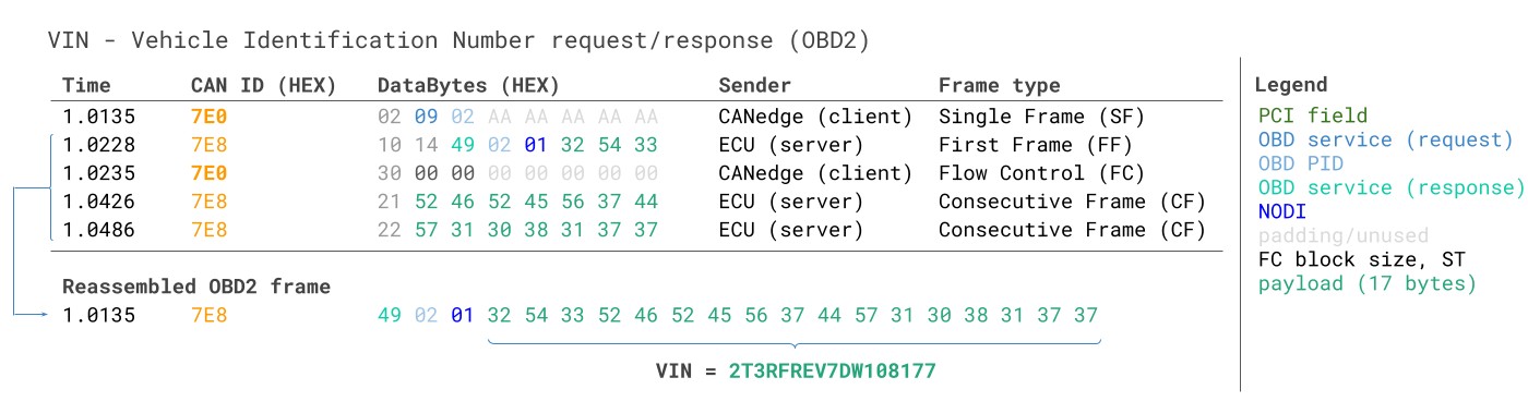 VIN Vehicle Identification Number OBD2 Example multi-frame
7.3. Requesting Multiple PIDs
External tools are allowed to request up to 6 mode 0x01 OBD2 PIDs in a single request frame. The ECU shall respond with data for supported PIDs (with unsupported PIDs left out of the response), if necessary across multiple frames as per ISO-TP.
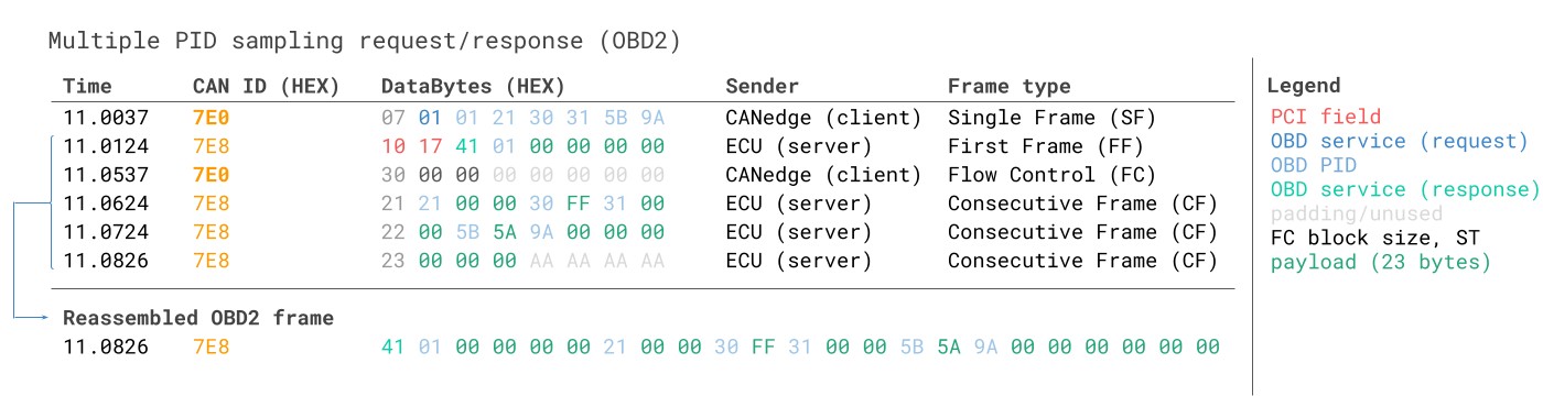 Requesting multiple PIDs in one request
7.4. Reading Diagnostic Trouble Codes (DTCs) with Mode 0x03
You can use OBD2 to request emissions-related Diagnostic Trouble Codes (DTCs) from using mode 0x03, i.e. ‘Show stored Diagnostic Trouble Codes’. No PID is included in the request. The targeted ECU(s) will then respond with the number of DTCs they have stored (including potentially 0 if they have none), with each DTC taking up 2 data bytes.
8. Real-World Applications of OBD2 Data
OBD2 data has numerous real-world applications, from individual vehicle maintenance to large-scale fleet management.
8.1. Use Cases for OBD2 Data Logging
- Fuel Efficiency: Monitoring fuel consumption to identify inefficient driving habits.
- Driver Behavior: Tracking speed, acceleration, and braking patterns to improve safety.
- Predictive Maintenance: Identifying potential mechanical issues before they lead to breakdowns.
- Vehicle Tracking: Real-time location tracking for security and fleet management.
- Emissions Monitoring: Ensuring compliance with environmental regulations.
8.2. Applications in Automotive Repair
OBD2 data enables technicians to quickly identify and diagnose issues. According to a 2022 report by the Automotive Management Institute (AMI), shops that utilize advanced diagnostic tools see a 25% increase in efficiency and a 15% increase in customer satisfaction.
8.3. Fleet Management
Fleet managers use OBD2 data to optimize vehicle usage, reduce maintenance costs, and improve driver safety. Real-time data helps in scheduling maintenance and preventing costly repairs.
9. Choosing the Right OBD2 Scanner
Selecting the right OBD2 scanner depends on your needs and budget. Key factors include compatibility, features, ease of use, and updates.
9.1. Types of OBD2 Scanners
- Basic Code Readers: Affordable, read and clear DTCs.
- Enhanced Scanners: Offer live data, freeze frame, and advanced diagnostics.
- Professional Scanners: Bi-directional control, advanced programming, and OEM-specific data.
- Wireless OBD2 Adapters: Connect to smartphones or tablets via Bluetooth or Wi-Fi.
9.2. Key Features to Look For
- Compatibility: Ensure the scanner supports your vehicle’s make and model.
- DTC Lookup: Built-in database for code definitions.
- Live Data: Real-time monitoring of sensors and parameters.
- Bi-Directional Control: Ability to send commands to vehicle systems.
- Updateability: Regular software updates for new vehicles and features.
9.3. Top OBD2 Scanner Brands
- Bosch: Known for professional-grade scanners.
- Snap-on: Industry-standard for advanced diagnostics.
- Autel: Offers a range of scanners for different needs.
- BlueDriver: Popular wireless adapter for smartphones.
10. Common OBD2 Problems and Solutions
While OBD2 systems are reliable, issues can arise. Common problems include connectivity issues, incorrect code readings, and software glitches.
10.1. Troubleshooting OBD2 Scanner Connection Issues
- Check the Connector: Ensure the OBD2 connector is clean and undamaged.
- Verify Power: Confirm the vehicle’s battery is charged and the ignition is on.
- Try Another Vehicle: Test the scanner on another vehicle to rule out scanner issues.
- Consult the Manual: Refer to the scanner’s manual for troubleshooting steps.
10.2. Dealing with Incorrect Code Readings
- Verify the Code: Use multiple sources to confirm the code definition.
- Check for Updates: Ensure the scanner has the latest software updates.
- Inspect Sensors: Physically inspect the related sensors and components.
- Seek Expert Advice: Consult with a professional technician for complex issues.
10.3. Addressing Software and Hardware Glitches
- Reboot the Scanner: Restart the scanner to clear temporary glitches.
- Update Software: Install the latest software version.
- Contact Support: Contact the manufacturer for hardware issues.
- Consider Replacement: If the scanner is old or damaged, consider replacing it.
FAQ: Your Questions About OBD2 Answered
Here are some frequently asked questions about OBD2 systems and their components.
Q1: What is the main purpose of the OBD2 system?
The primary purpose of the OBD2 system is to monitor vehicle emissions and diagnose engine-related problems. It helps technicians and vehicle owners identify issues by providing diagnostic trouble codes (DTCs) and real-time data.
Q2: Where is the OBD2 connector located in my car?
The OBD2 connector is typically located within 2 feet of the steering wheel, often under the dashboard on the driver’s side, inside the center console, or behind an ashtray or panel.
Q3: How do I read and interpret OBD2 codes?
Connect an OBD2 scanner to the OBD2 connector, turn on the ignition, and select “Read Codes” on the scanner. Record the DTCs and use a reliable database to look up their meanings.
Q4: What should I do after reading a DTC?
After reading a DTC, research the code to understand the potential issue. Inspect related components, perform necessary repairs, and clear the code using the scanner. Monitor the vehicle to ensure the problem does not return.
Q5: Can I clear OBD2 codes without fixing the problem?
While you can clear OBD2 codes, it is not recommended to do so without addressing the underlying issue. Clearing codes without fixing the problem can mask the issue and lead to further damage.
Q6: What is the difference between a basic OBD2 scanner and a professional scanner?
Basic OBD2 scanners read and clear DTCs, while professional scanners offer advanced features like live data, bi-directional control, and OEM-specific data. Professional scanners are more comprehensive but also more expensive.
Q7: How often should I scan my car with an OBD2 scanner?
You should scan your car with an OBD2 scanner whenever the check engine light comes on or if you suspect any engine-related issues. Regular scanning can help catch problems early and prevent costly repairs.
Q8: Can OBD2 scanners be used on all cars?
OBD2 scanners are generally compatible with most cars manufactured after 1996 in the United States. However, compatibility can vary depending on the make, model, and year of the vehicle.
Q9: What is live data and why is it important?
Live data refers to real-time monitoring of sensors and parameters in your vehicle. It is important because it allows technicians to see how the engine and other systems are performing, helping to diagnose intermittent issues and verify repairs.
Q10: Are there any risks associated with using an OBD2 scanner?
When used correctly, OBD2 scanners are generally safe. However, incorrect use or faulty scanners can potentially cause electrical issues. Always follow the manufacturer’s instructions and use reputable brands.
Take Action Today
Don’t let vehicle issues slow you down. Contact CAR-DIAGNOSTIC-TOOL.EDU.VN today for expert advice on selecting the right OBD2 scanner, understanding diagnostic codes, and accessing comprehensive repair guides. Our team is ready to provide remote support and hands-on training to help you master vehicle diagnostics. Improve your efficiency, increase your revenue, and build trust with your customers by diagnosing problems accurately and quickly.
Ready to get started?
- Visit our website: CAR-DIAGNOSTIC-TOOL.EDU.VN
- Call our US support office: 1100 Congress Ave, Austin, TX 78701, United States
- Contact us on Whatsapp: +1 (641) 206-8880
Let CAR-DIAGNOSTIC-TOOL.EDU.VN be your partner in automotive excellence.