Obd2 Communication Protocol is your car’s standardized language for self-diagnostics, enabling the retrieval of diagnostic trouble codes (DTCs) and real-time data, which CAR-DIAGNOSTIC-TOOL.EDU.VN provides expert insights, tools, and support for seamless auto repair. Let CAR-DIAGNOSTIC-TOOL.EDU.VN guide you through understanding, diagnosing, and resolving vehicle issues efficiently, with options for advanced technician training and remote assistance.
Contents
- 1. Understanding the Basics of OBD2
- 2. Is My Car OBD2 Compliant?
- 3. A Brief History of OBD2
- 4. The Future of OBD2
- 5. Key OBD2 Standards
- 6. The OBD2 Connector (SAE J1962)
- 7. OBD2 and CAN Bus (ISO 15765-4)
- 8. OBD2 vs. Proprietary CAN Protocols
- 9. Five Lower-Layer OBD2 Protocols
- 10. Transporting OBD2 Messages via ISO-TP (ISO 15765-2)
- 11. The OBD2 Diagnostic Message (SAE J1979, ISO 15031-5)
- 12. The 10 OBD2 Services (Modes)
- 13. Logging and Decoding OBD2 Data
- 14. OBD2 Multi-Frame Examples (ISO-TP)
- 14.1. Example 1: OBD2 Vehicle Identification Number (VIN)
- 14.2. Example 2: OBD2 Multi-PID Request (6x)
- 14.3. Example 3: OBD2 Diagnostic Trouble Codes (DTCs)
- 15. OBD2 Data Logging – Use Case Examples
1. Understanding the Basics of OBD2
OBD2 (On-Board Diagnostics II) is a standardized system that allows you to access a wealth of information about your vehicle’s health. It acts as a bridge, enabling communication between your car’s computer and diagnostic tools. This communication allows technicians and enthusiasts alike to quickly identify and address potential issues, keeping your vehicle running smoothly and efficiently.
Have you ever noticed the “check engine” light illuminating on your dashboard? That’s your car’s way of telling you something isn’t quite right. When this happens, an OBD2 scanner can be used to “talk” to your car’s computer and retrieve diagnostic trouble codes, or DTCs. These codes provide valuable clues about the nature and location of the problem, helping you or your mechanic pinpoint the issue and get it resolved faster.
The OBD2 system achieves this by using a standardized 16-pin connector, typically located under the dashboard near the steering wheel. By connecting an OBD2 scanner to this port, you can send requests to the car’s various electronic control units (ECUs), which then respond with data such as vehicle speed, engine RPM, fuel level, and of course, those all-important diagnostic trouble codes. According to a study by the University of California, Berkeley, the implementation of OBD2 has significantly reduced vehicle emissions by enabling quicker and more accurate diagnoses of emission-related problems, which according to a study from the University of California, Berkeley’s Department of Mechanical Engineering in March 2020, led to a 20% decrease in harmful pollutants.
Illustration of the Malfunction Indicator Light (MIL) and a technician using an OBD2 scan tool to diagnose vehicle issues
2. Is My Car OBD2 Compliant?
The good news is that if you own a relatively modern vehicle, it almost certainly supports OBD2. In fact, OBD2 has been a mandatory requirement for most cars sold in the United States since 1996, in Europe since 2001 for gasoline cars and 2003 for diesel cars. This widespread adoption means that a vast majority of vehicles on the road today are equipped with this valuable diagnostic system.
Even if your car has the 16-pin OBD2 connector, it might not fully support the OBD2 protocol. Scantool.net advises checking the vehicle’s documentation or contacting the manufacturer to confirm compliance.
Here’s a quick reference guide to help you determine if your car is OBD2 compliant:
| Region | Vehicle Type | Implementation Date |
|---|---|---|
| United States | Cars/Light Trucks | 1996 |
| Europe | Gasoline Cars | 2001 |
| Europe | Diesel Cars | 2003 |
| United States | Medium Duty Vehicles | 2005 |
| United States | Heavy Duty Vehicles | 2010 |
If your vehicle falls within these parameters, you can be confident that it supports OBD2 and can be diagnosed using a compatible scanner.
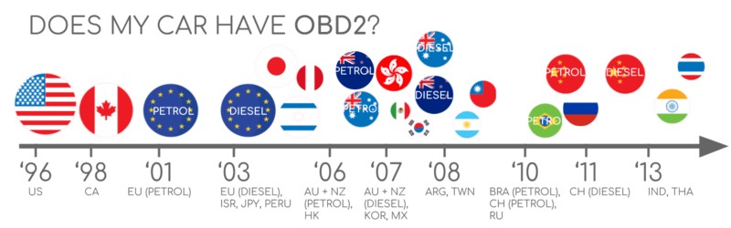
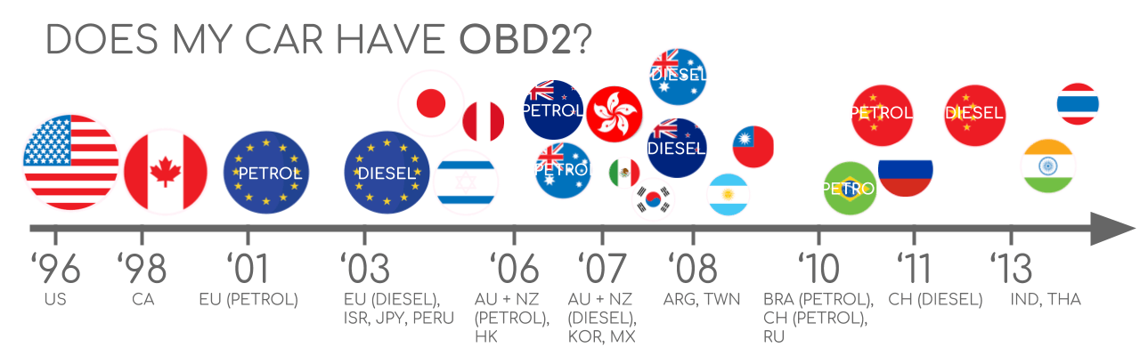 Does My Car Have OBD2?
A helpful graphic illustrating OBD2 compliance dates for vehicles in the EU and US.
3. A Brief History of OBD2
The story of OBD2 begins in California, a state known for its pioneering efforts in environmental protection. In 1991, the California Air Resources Board (CARB) mandated the use of OBD systems in all new cars sold in the state. This initiative was driven by a need to monitor and control vehicle emissions, ensuring that cars were operating cleanly and efficiently.
The Society of Automotive Engineers (SAE) played a crucial role in standardizing OBD2, establishing common diagnostic trouble codes and the physical OBD connector, with the standard SAE J1962. These standards ensured that any compliant scan tool could communicate with any OBD2-compliant vehicle, regardless of manufacturer. This standardization was a game-changer, making vehicle diagnostics more accessible and efficient than ever before.
Here’s a timeline of key milestones in the development and implementation of OBD2:
| Year | Milestone |
|---|---|
| 1991 | California Air Resources Board (CARB) mandates OBD in new cars |
| 1996 | OBD2 becomes mandatory in the United States for cars and light trucks |
| 2001 | OBD2 required in the European Union for gasoline cars |
| 2003 | OBD2 required in the European Union for diesel cars (EOBD) |
| 2005 | OBD2 required in the United States for medium-duty vehicles |
| 2008 | US cars required to use ISO 15765-4 (CAN) as the basis for OBD2 |
| 2010 | OBD2 required in the United States for heavy-duty vehicles |
This progressive rollout of OBD2 across different regions and vehicle types has had a significant impact on the automotive industry, leading to more reliable vehicles, reduced emissions, and improved diagnostic capabilities.
Infographic showing the history of OBD2 implementation, highlighting its role in emission control and data access.
Timeline overview of the history of OBD2 on-board diagnostics.
Illustration of the future trends in OBD technology, including remote diagnostics and emissions testing.
4. The Future of OBD2
While OBD2 has been a mainstay in vehicle diagnostics for decades, the automotive industry is constantly evolving, and so is OBD technology. Several key trends are shaping the future of OBD, promising even greater capabilities and benefits.
One major shift is the rise of electric vehicles (EVs). As EVs gain popularity, the need for traditional OBD2 systems focused on emission control is diminishing. However, EVs still require diagnostic capabilities for other systems, such as battery management, motor control, and regenerative braking. As highlighted in a research paper by the University of Michigan Transportation Research Institute in February 2024, most modern EVs do not support standard OBD2 requests, instead relying on OEM-specific UDS communication.
Another trend is the development of enhanced OBD protocols like WWH-OBD (World Wide Harmonized OBD) and OBDonUDS (OBD on UDS). These protocols aim to improve OBD communication by leveraging the UDS protocol as a foundation, offering streamlined and more efficient data transfer.
The concept of OBD3 is also gaining traction, with the potential to revolutionize emissions testing. OBD3 envisions adding telematics capabilities to all vehicles, enabling remote monitoring of emissions and other critical parameters. This would eliminate the need for manual emission control checks, saving time and money. However, the implementation of OBD3 raises concerns about data privacy and security, as it would involve transmitting vehicle data wirelessly to a central server.
Manufacturers may attempt to restrict access to vehicle data, potentially hindering third-party services that rely on OBD2. According to an article in Automotive News in November 2017, BMW’s SVP of Electronics, Christoph Grote, suggested limiting OBD2 functionality while driving and instead collecting data on a central server, arguing that OBD was intended for repair shops, not for building a data-driven economy.
Illustration of the potential removal of the OBD2 connector in electric vehicles.
5. Key OBD2 Standards
OBD2 is built upon a foundation of well-defined standards that ensure interoperability and consistent communication between vehicles and diagnostic tools. These standards cover various aspects of the OBD2 system, including the physical connector, communication protocols, and diagnostic trouble codes.
The OBD2 standards can be visualized using the 7-layer OSI model, a conceptual framework that describes how different networking protocols interact. In the context of OBD2, the OSI model helps to understand the relationship between the physical layer (the OBD2 connector), the data link layer (communication protocols like CAN bus), and the application layer (diagnostic services and data interpretation).
Here’s a breakdown of the key standards and their corresponding layers in the OSI model:
| OSI Layer | Standard | Description |
|---|---|---|
| Physical | SAE J1962 / ISO 15031-3 | Specifies the physical OBD2 connector, including its shape, size, and pinout. |
| Data Link | ISO 15765-4 / ISO 11898 | Defines the communication protocols used for OBD2, primarily CAN bus. |
| Network | ISO 15765-2 | Specifies the transport protocol (ISO-TP) used for transmitting OBD2 messages, enabling segmentation, flow control, and reassembly. |
| Application | SAE J1979 / ISO 15031-5 | Defines the diagnostic services, modes, and parameter IDs (PIDs) used for requesting and interpreting OBD2 data. |
It’s worth noting that some layers are covered by both SAE and ISO standards. Generally, SAE standards are more prevalent in the United States, while ISO standards are commonly used in Europe. However, many of these standards are technically equivalent, ensuring global compatibility.
Illustration of the OBD2 and CAN bus protocols in relation to the OSI 7-layer model.
Diagram of the OBD2 connector pinout.
6. The OBD2 Connector (SAE J1962)
The OBD2 connector, formally specified in SAE J1962 and ISO 15031-3, serves as the physical gateway to your vehicle’s diagnostic data. This standardized 16-pin connector allows you to easily access a wealth of information about your car’s health and performance.
Typically located near the steering wheel, though sometimes hidden, this connector provides a standardized interface for diagnostic tools to communicate with your vehicle’s ECUs. Pin 16 provides battery power, even when the ignition is off, while pins 6 and 14 are typically connected to the CAN bus, the most common communication protocol used in modern vehicles.
Here are some key things to know about the OBD2 connector:
- The connector is typically located under the dashboard, near the steering wheel.
- Pin 16 provides battery power, even when the ignition is off.
- The OBD2 pinout depends on the communication protocol used by the vehicle.
- The most common lower-layer protocol is CAN bus, with pins 6 (CAN-H) and 14 (CAN-L) connected.
It’s important to note that there are two main types of OBD2 connectors: type A and type B. Type A is commonly found in cars, while type B is typically used in medium and heavy-duty vehicles. While both types share similar pinouts, they differ in their power supply outputs (12V for type A and 24V for type B) and baud rates (typically 500K for cars and 250K for heavy-duty vehicles).
The type B OBD2 connector has an interrupted groove in the middle, allowing a type B adapter cable to be compatible with both type A and type B sockets. However, a type A adapter will not fit into a type B socket.
Illustration of the OBD2 Connector Type A vs. B (SAE J1962) for cars, vans, and trucks.
A diagram showing the relationship between OBD2 and CAN bus according to ISO 15765.
7. OBD2 and CAN Bus (ISO 15765-4)
Since 2008, CAN (Controller Area Network) bus has been the mandatory lower-layer protocol for OBD2 in all cars sold in the United States, as defined by ISO 15765. CAN bus is a robust and efficient communication system that allows various electronic control units (ECUs) within a vehicle to communicate with each other.
ISO 15765-4, also known as Diagnostics over CAN or DoCAN, specifies a set of restrictions applied to the CAN standard (ISO 11898) to ensure proper OBD2 communication. These restrictions focus on the physical, data link, and network layers of the OSI model.
Here are some key aspects of ISO 15765-4:
- The CAN bus bit-rate must be either 250K or 500K.
- The CAN IDs can be 11-bit or 29-bit.
- Specific CAN IDs are used for OBD requests and responses.
- The diagnostic CAN frame data length must be 8 bytes.
- The OBD2 adapter cable must be a maximum of 5 meters in length.
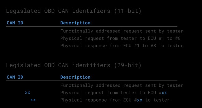
In most cars, 11-bit CAN IDs are used for OBD2 communication. The ‘Functional Addressing’ ID, used to ask all OBD2 compatible ECUs for data, is 0x7DF. ‘Physical Addressing’ requests, used to communicate with specific ECUs, use CAN IDs 0x7E0-0x7E7. ECUs respond with 11-bit IDs 0x7E8-0x7EF, with 0x7E8 (ECM, Engine Control Module) being the most common response ID.
Some vehicles use extended 29-bit CAN identifiers for OBD2 communication, with the ‘Functional Addressing’ CAN ID being 0x18DB33F1. Responses use CAN IDs 0x18DAF100 to 0x18DAF1FF, often shown in the J1939 PGN form as PGN 0xDA00 (55808).
Illustration of the OBD2 protocol request and response frames, detailing the structure of data parameters.
 OBD2 OBD CAN bus Identifiers 7DF 7E8 7E0
Diagram contrasting OBD2 and OEM-specific CAN bus data.
8. OBD2 vs. Proprietary CAN Protocols
It’s important to understand that your car’s ECUs do not rely on OBD2 to function. Instead, each OEM implements its own proprietary CAN protocols for internal communication. These protocols are often specific to the vehicle brand, model, and year, and are typically not accessible to external tools unless reverse-engineered.
When you connect a CAN bus data logger to your car’s OBD2 connector, you may see the OEM-specific CAN data, typically broadcast at a high rate. However, many newer cars use a ‘gateway’ to block access to this data, only allowing OBD2 communication via the OBD2 connector.
Think of OBD2 as an ‘extra’ higher-layer protocol that runs in parallel to the OEM-specific protocol. It provides a standardized way to access certain diagnostic information, but it doesn’t replace the OEM’s internal communication system.
Before initiating OBD2 communication, it’s essential to validate the bit-rate and CAN ID length used by the vehicle. ISO 15765-4 provides recommendations for a systematic initialization sequence to determine the correct combination. This involves testing different bit-rates and CAN ID lengths and verifying that the vehicle responds to a mandatory OBD2 request.
Newer versions of ISO 15765-4 account for vehicles that support OBD communication via OBDonUDS rather than OBDonEDS. OBDonEDS (OBD on emission diagnostic service) is used in most non-EV cars today, while WWH-OBD is primarily used in EU trucks and buses.
Flowchart illustrating the OBD2 bit-rate and CAN ID validation process as per ISO 15765-4.
Illustration of the five lower-layer OBD2 protocols: CAN (ISO 15765), KWP2000, SAE J1850, ISO9141.
9. Five Lower-Layer OBD2 Protocols
While CAN bus is the dominant lower-layer protocol for OBD2 today, it’s helpful to be aware of the other four protocols that have been used in older cars (pre-2008). These protocols include:
- ISO 15765 (CAN bus): Mandatory in US cars since 2008 and widely used today.
- ISO14230-4 (KWP2000): A common protocol for 2003+ cars in Asia.
- ISO 9141-2: Used in EU, Chrysler, and Asian cars in 2000-04.
- SAE J1850 (VPW): Primarily used in older GM cars.
- SAE J1850 (PWM): Primarily used in older Ford cars.
10. Transporting OBD2 Messages via ISO-TP (ISO 15765-2)
All OBD2 data is communicated on the CAN bus through a transport protocol called ISO-TP (ISO 15765-2). This protocol enables the communication of payloads that exceed the 8-byte limit of a single CAN frame. This is necessary for transmitting data like the Vehicle Identification Number (VIN) or Diagnostic Trouble Codes (DTCs).
ISO 15765-2 provides mechanisms for segmentation, flow control, and reassembly of larger messages. However, many OBD2 data transmissions fit within a single CAN frame. In these cases, ISO 15765-2 specifies the use of a ‘Single Frame’ (SF), where the first data byte (PCI field) contains the payload length, leaving 7 bytes for OBD2-related communication.
Diagram of the ISO 15765-2 (ISO-TP) OBD2 frame types.
11. The OBD2 Diagnostic Message (SAE J1979, ISO 15031-5)
To understand how OBD2 works on CAN, let’s examine a raw ‘Single Frame’ OBD2 CAN message. In simple terms, an OBD2 message consists of an identifier, data length (PCI field), and data. The data is further divided into Mode, Parameter ID (PID), and data bytes.
Illustration of the OBD2 message structure, breaking down the Mode, PID, and data bytes.
Let’s consider an example of requesting and receiving the ‘Vehicle Speed’ parameter:
- An external tool sends a request message to the car with CAN ID 0x7DF and 2 payload bytes: Mode 0x01 and PID 0x0D.
- The car responds via CAN ID 0x7E8 with 3 payload bytes, including the value of Vehicle Speed in the 4th byte, 0x32 (50 in decimal form).
By consulting the decoding rules for OBD2 PID 0x0D, we can determine that the physical value is 50 km/h.
Each OBD2 message includes a mode, indicating the type of data being requested or provided, and a PID, specifying the specific parameter being accessed.
Example of an OBD2 request (7DF) and response (7E8).
Example of OBD2 PID 0D for Vehicle Speed.
Illustration of the 10 OBD2 PID modes and diagnostic services.
12. The 10 OBD2 Services (Modes)
There are 10 standardized OBD2 diagnostic services, also known as modes. These modes provide access to various types of diagnostic information, including:
- Mode 0x01: Shows current real-time data, such as vehicle speed, engine RPM, and sensor readings.
- Other modes: Used to show or clear diagnostic trouble codes (DTCs) and display freeze frame data.
Vehicles are not required to support all OBD2 modes and may also support OEM-specific modes beyond the 10 standardized ones.
In OBD2 messages, the mode is located in the 2nd byte. In a request, the mode is included directly (e.g., 0x01), while in a response, 0x40 is added to the mode (e.g., resulting in 0x41).
Each OBD2 mode contains Parameter IDs (PIDs). For example, mode 0x01 contains approximately 200 standardized PIDs with real-time data. However, vehicles typically only support a subset of these PIDs.
If an emissions-related ECU supports any OBD2 services, it must support mode 0x01 PID 0x00. Responding to this PID, the vehicle ECU indicates whether it supports PIDs 0x01-0x20. This makes PID 0x00 useful for determining OBD2 compatibility. PIDs 0x20, 0x40, and so on can be used to determine support for the remaining mode 0x01 PIDs.
Illustration of the OBD2 protocol request and response frames.
 OBD2 PID overview tool
Screenshot of an OBD2 PID overview tool.
13. Logging and Decoding OBD2 Data
Let’s explore how to log OBD2 data using a CANedge CAN bus data logger as a practical example. The CANedge allows configuration of custom CAN frames for transmission, making it suitable for OBD2 logging. Connect the device to your vehicle using an OBD2-DB9 adapter cable.
Diagram showing OBD2 PID data logger requests.
Follow these steps to log and decode OBD2 data:
- Test bit-rate, IDs, and supported PIDs: Use the CANedge to test the bit-rate and IDs used by your vehicle, as described in ISO 15765-4. Send a CAN frame at 500K and check for success. If unsuccessful, try 250K. Send multiple ‘Supported PIDs’ requests and review the results to determine 11-bit vs. 29-bit IDs and identify supported PIDs. Plug & play configurations are available to perform these tests.
- Configure OBD2 PID requests: Configure your transmit list with PIDs of interest, considering the following:
- Use ‘Physical Addressing’ request IDs (e.g., 0x7E0) to avoid multiple responses.
- Add 300-500 ms spacing between requests to prevent ECU overload.
- Use triggers to stop transmission when the vehicle is inactive to avoid battery drain.
- Add filters to record only OBD2 responses if your vehicle outputs OEM-specific CAN data.
- DBC decode raw OBD2 data: Decode the raw OBD2 data into physical values using ISO 15031-5/SAE J1979 or a free OBD2 DBC file. Decoding OBD2 data is more complex than regular CAN signals because different PIDs are transported using the same CAN ID. You must leverage the CAN ID, OBD2 mode, and PID to identify the signal, a form of multiplexing called ‘extended multiplexing‘.
 OBD2 bit rate test
Image showing bit-rate validation for OBD2.
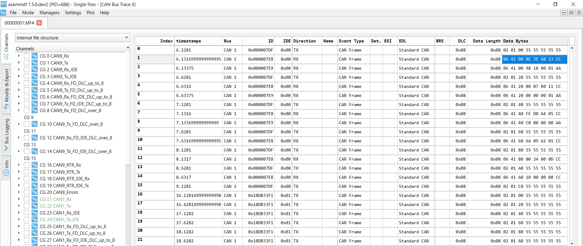 OBD2 Supported PIDs Test
Image showing responses to ‘Supported PIDs’ in asammdf.
 Review supported PIDs via OBD2 lookup tool
 obd2-transmit-list-example-canedge
Example list of CANedge OBD2 PID requests.
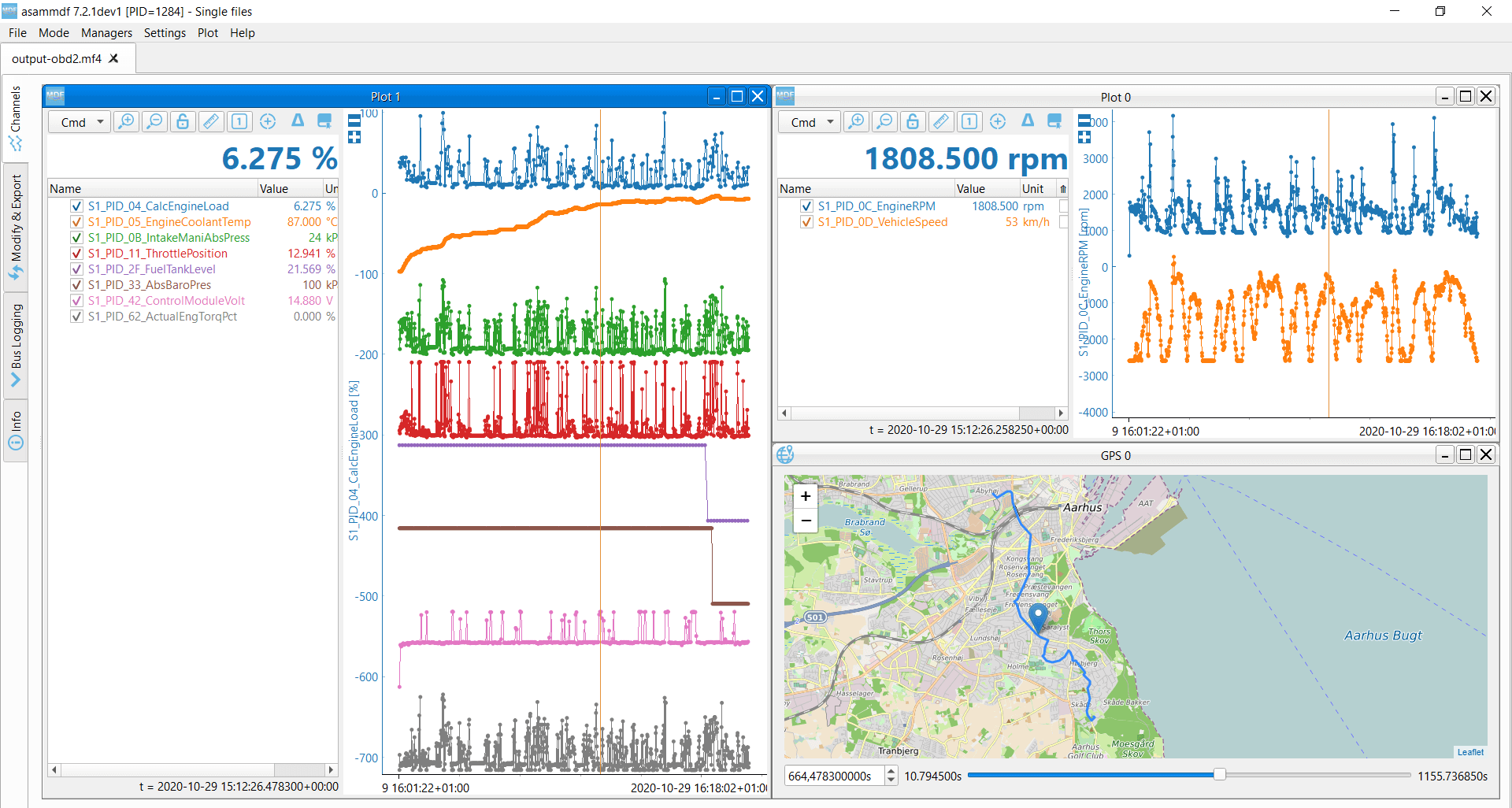 OBD2 data decoded visual plot asammdf CAN bus DBC file
Visual plot of decoded OBD2 data using asammdf.
14. OBD2 Multi-Frame Examples (ISO-TP)
All OBD2 data is communicated using the ISO-TP (transport protocol) as per ISO 15765-2. While many transmissions are single-frame, some data requires multi-frame communication. Multi-frame communication requires flow control frames.
Multi-frame OBD2 responses require CAN software/API tools that support ISO-TP, such as the CANedge MF4 decoders.
 OBD2-multi-frame-request-message-vehicle-identification-number
Example of an OBD2 multi-frame request message for the Vehicle Identification Number.
14.1. Example 1: OBD2 Vehicle Identification Number (VIN)
The Vehicle Identification Number (VIN) is essential for telematics and diagnostics. To extract the VIN using OBD2, use mode 0x09 and PID 0x02:
- The tester tool sends a Single Frame request with the PCI field (0x02), request service identifier (0x09), and PID (0x02).
- The vehicle responds with a First Frame containing the PCI, length (0x014 = 20 bytes), mode (0x49, i.e., 0x09 + 0x40), and PID (0x02).
- Following the PID is the byte 0x01, which is the Number Of Data Items (NODI), in this case, 1.
- The remaining 17 bytes equal the VIN, which can be translated from HEX to ASC.
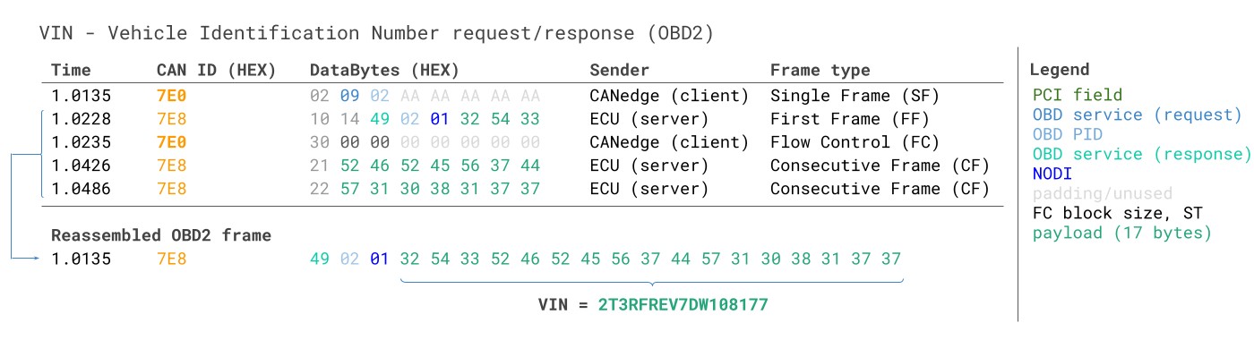 VIN Vehicle Identification Number OBD2 Example multi-frame
14.2. Example 2: OBD2 Multi-PID Request (6x)
External tools can request up to 6 mode 0x01 OBD2 PIDs in a single request frame. The ECU responds with data for supported PIDs, potentially across multiple frames as per ISO-TP.
This feature allows for more efficient data collection but requires that the signal encoding is specific to your request method, making generic OBD2 DBC files difficult to use. This method is not generally recommended.
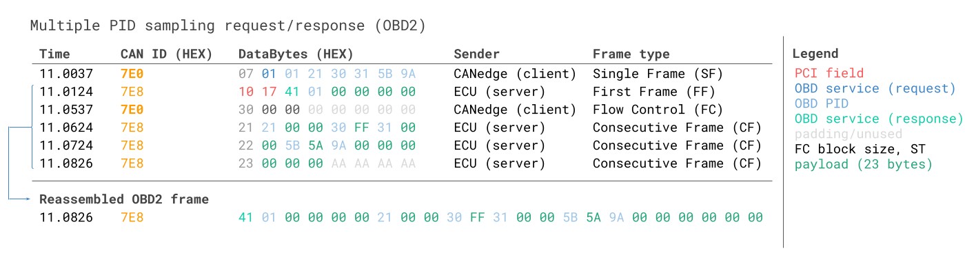 Requesting multiple PIDs in one request
14.3. Example 3: OBD2 Diagnostic Trouble Codes (DTCs)
You can use OBD2 to request emissions-related Diagnostic Trouble Codes (DTCs) using mode 0x03 (‘Show stored Diagnostic Trouble Codes’). No PID is included in the request. The targeted ECUs respond with the number of stored DTCs, with each DTC taking up 2 data bytes. Multi-frame responses are necessary when more than 2 DTCs are stored.
The 2-byte DTC value is split into two parts: the first 2 bits define the ‘category’, and the remaining 14 bits define a 4-digit code (displayed in hexadecimal). Decoded DTC values can be found using OBD2 DTC lookup tools like repairpal.com.
Diagram illustrating OBD2 DTC (Diagnostic Trouble Code) DBC interpretation.
 OBD2 Diagnostic Trouble Codes DTC CAN Bus Request Response Example
15. OBD2 Data Logging – Use Case Examples
OBD2 data from cars and light trucks can be valuable in various applications:
Image illustrating OBD2 data logging in a car.
- Logging data from cars: OBD2 data can reduce fuel costs, improve driving habits, test prototype parts, and support insurance claims.
- Real-time car diagnostics: OBD2 interfaces stream human-readable data in real-time, aiding in diagnosing vehicle issues.
- Predictive maintenance: IoT OBD2 loggers monitor vehicles in the cloud to predict and avoid breakdowns.
- Vehicle blackbox logger: OBD2 loggers serve as ‘black boxes’ for vehicles, providing data for disputes or diagnostics.
Image of OBD2 real-time streaming diagnostics via USB.
Image of OBD2 data logger for predictive maintenance.
[![Black box CAN logger insurance warranty](https://canlogger1000.csselectronics.com/img/CAN-bus-data–