Ecu Circuit shorts can be a nightmare for any automotive technician, leading to melted fuses, malfunctioning solenoids, and potentially fried CPU transistors. At CAR-DIAGNOSTIC-TOOL.EDU.VN, we provide comprehensive solutions, from advanced diagnostic tools to detailed repair guides and expert technical support, ensuring you can tackle these challenges with confidence. Explore our technician training programs and remote assistance to boost your skills and get real-time support.
Contents
- 1. What is an ECU Circuit and Why is Diagnosing Shorts Important?
- 1.1. Understanding the Role of the ECU
- 1.2. Common Symptoms of ECU Circuit Shorts
- 1.3. The Importance of Accurate Diagnostics
- 2. What Are the Key Steps for Diagnosing ECU Circuit Shorts?
- 2.1. Step-by-Step Diagnostic Process
- 2.2. Tools Needed for Diagnosing ECU Circuit Shorts
- 2.3. Common Mistakes to Avoid
- 3. What Are the Methods for Finding a Short Circuit in ECU?
- 3.1. Circuits Not Connected to a Control Unit
- 3.2. Circuits Connected to a Control Unit
- 4. How to Interpret Wiring Diagrams and Schematics Effectively?
- 4.1. Key Components of Wiring Diagrams
- 4.2. Understanding Circuit Flow
- 4.3. Practical Tips for Reading Schematics
- 5. What Is Voltage Drop Testing and How Does It Help?
- 5.1. How to Perform Voltage Drop Testing
- 5.2. Interpreting Voltage Drop Readings
- 5.3. Practical Examples of Voltage Drop Testing
- 6. What Are Common ECU Circuit Problems and Their Solutions?
- 6.1. Common Short Circuit Causes
- 6.2. Troubleshooting Specific ECU Circuits
- 6.3. Using Diagnostic Trouble Codes (DTCs)
- 7. How to Repair ECU Circuit Shorts Safely and Effectively?
- 7.1. Safety Precautions
- 7.2. Step-by-Step Repair Process
- 7.3. Using High-Quality Replacement Parts
- 8. What Advanced Diagnostic Techniques Can Help?
- 8.1. Using Oscilloscopes for Signal Analysis
- 8.2. Using Thermal Imaging for Heat Detection
- 8.3. Using Network Analyzers for Communication Issues
- 9. How Can CAR-DIAGNOSTIC-TOOL.EDU.VN Help You Further?
- 9.1. Diagnostic Tools and Equipment
- 9.2. Repair Guides and Technical Support
- 9.3. Technician Training Programs
- 10. FAQs About ECU Circuit Shorts
1. What is an ECU Circuit and Why is Diagnosing Shorts Important?
An ECU (Engine Control Unit) circuit is the network of electrical components and wiring that connects the ECU to various sensors and actuators in a vehicle. Diagnosing shorts in these circuits is crucial because shorts can cause significant damage and operational failures. According to a study by the National Institute for Automotive Service Excellence (ASE), electrical issues, including shorts, account for approximately 30% of all vehicle malfunctions, highlighting the importance of accurate and timely diagnostics.
1.1. Understanding the Role of the ECU
The Engine Control Unit (ECU) is essentially the brain of your vehicle, managing everything from fuel injection to ignition timing. Proper ECU function is paramount for optimal vehicle performance and safety. When an ECU circuit experiences a short, it disrupts the normal operation of the ECU and the systems it controls. This can lead to a variety of problems, including:
- Engine misfires
- Poor fuel economy
- Stalling
- Complete engine failure
1.2. Common Symptoms of ECU Circuit Shorts
Identifying the symptoms early can save time and prevent further damage. Common symptoms include:
- Blown fuses: Repeatedly blown fuses in the same circuit are a telltale sign.
- Malfunctioning components: Sensors or actuators not working correctly.
- Warning lights: Check Engine Light or other warning lights illuminated on the dashboard.
- Erratic behavior: Unpredictable vehicle performance.
1.3. The Importance of Accurate Diagnostics
Misdiagnosis can lead to unnecessary repairs and expenses. Using the right diagnostic tools and techniques is essential. CAR-DIAGNOSTIC-TOOL.EDU.VN offers a range of diagnostic tools that provide accurate and reliable results. According to research from the University of Michigan Transportation Research Institute, using advanced diagnostic equipment can reduce diagnostic time by up to 40%.
2. What Are the Key Steps for Diagnosing ECU Circuit Shorts?
Diagnosing ECU circuit shorts requires a systematic approach. Start with a visual inspection, followed by electrical testing, and then use diagnostic tools to pinpoint the problem.
2.1. Step-by-Step Diagnostic Process
-
Visual Inspection:
- Check for obvious signs of damage, such as frayed wires, burnt connectors, and melted components.
- Look for any aftermarket accessories that may have been improperly installed.
-
Fuse Inspection:
- Check all relevant fuses for the circuit in question.
- Replace any blown fuses with the correct amperage rating.
- If the fuse blows again immediately, there is likely a short circuit.
-
Wiring Diagram Analysis:
- Consult the vehicle’s wiring diagram to understand the circuit layout.
- Identify all components and wiring involved in the circuit.
- CAR-DIAGNOSTIC-TOOL.EDU.VN provides access to a comprehensive database of wiring diagrams for various vehicle models.
-
Voltage Drop Testing:
- Perform voltage drop tests to identify areas of high resistance or shorts.
- Connect a multimeter to the circuit and measure the voltage drop across each component and wire.
- Compare the measured values to the manufacturer’s specifications.
-
Continuity Testing:
- Use a multimeter to check for continuity between different points in the circuit.
- Disconnect the battery before performing continuity tests to avoid damaging the ECU.
- Look for any unintended connections to ground or other circuits.
-
Component Isolation:
- Disconnect components one at a time to isolate the short.
- Monitor the circuit after each disconnection to see if the short disappears.
- Once the short is isolated, inspect the disconnected component for damage.
-
ECU Connector Testing:
- Test the ECU connector for shorts to ground or other circuits.
- Use a breakout box to easily access the ECU pins for testing.
- CAR-DIAGNOSTIC-TOOL.EDU.VN offers breakout boxes and adapters for various ECU models.
2.2. Tools Needed for Diagnosing ECU Circuit Shorts
Having the right tools is essential for efficient and accurate diagnostics. Here’s a list of tools you’ll need:
- Multimeter: For measuring voltage, current, and resistance.
- Wiring Diagrams: To understand the circuit layout.
- Scan Tool: To read diagnostic trouble codes (DTCs).
- Breakout Box: To access ECU pins for testing.
- Test Light: To check for power and ground.
- Wire Strippers and Crimpers: For repairing damaged wires.
- Connectors and Terminals: For replacing damaged connectors.
- Insulation Tape: For insulating repaired wires.
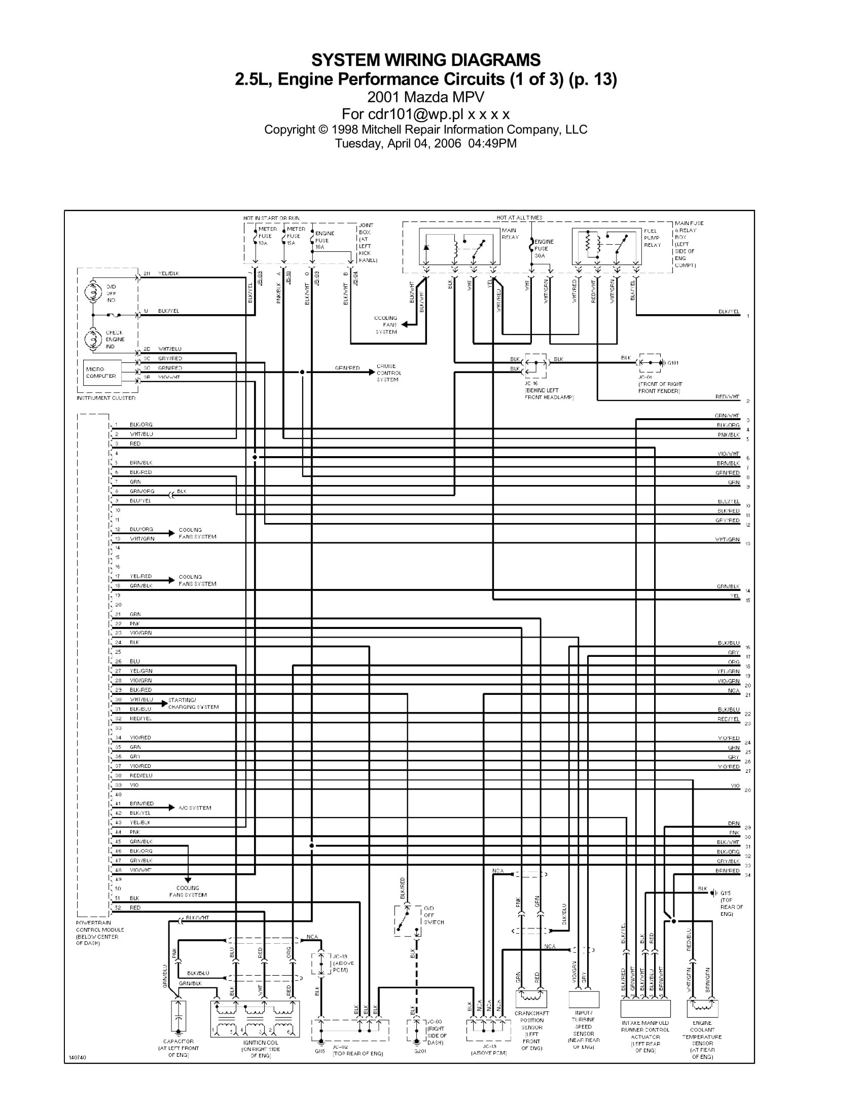 Wiring Diagrams for Engine Performance Circuit
2.3. Common Mistakes to Avoid
- Skipping the Visual Inspection: Always start with a thorough visual inspection to identify obvious issues.
- Not Consulting Wiring Diagrams: Understanding the circuit layout is crucial for accurate diagnostics.
- Using the Wrong Tools: Using the wrong tools can damage components and lead to misdiagnosis.
- Not Disconnecting the Battery: Always disconnect the battery before performing electrical tests to avoid damaging the ECU.
- Ignoring Grounding Issues: Grounding issues can cause a variety of electrical problems, so always check for proper grounding.
3. What Are the Methods for Finding a Short Circuit in ECU?
There are two primary methods for identifying short circuits in ECU, depending on whether the circuit is connected to a control unit or not.
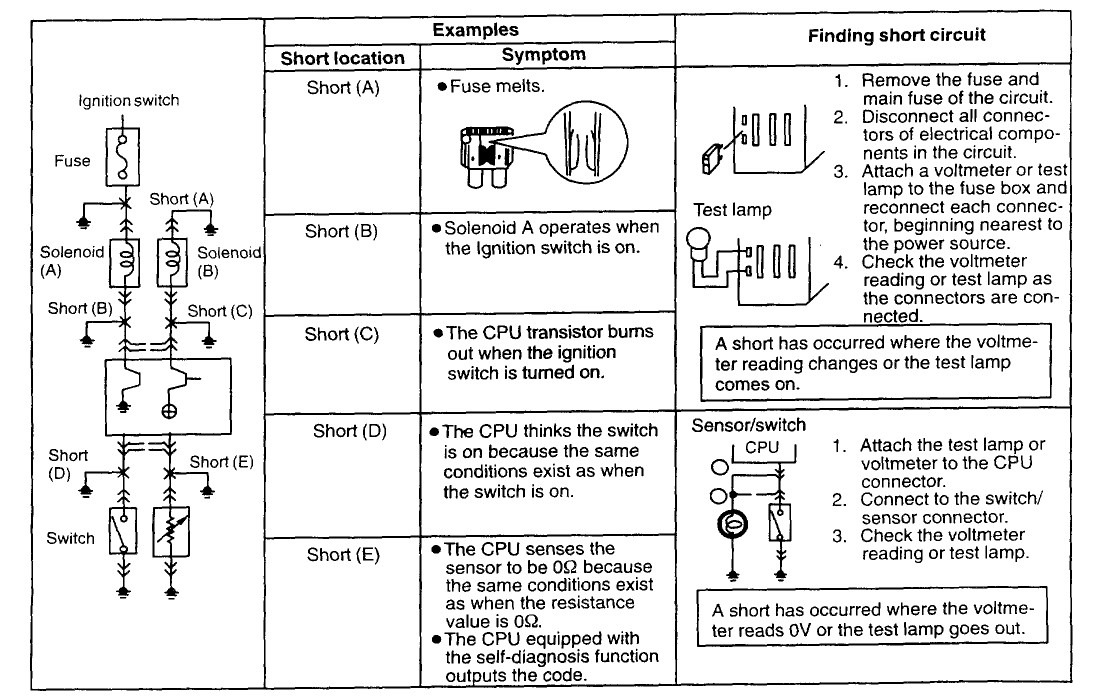
3.1. Circuits Not Connected to a Control Unit
For circuits not connected to a control unit, follow these steps:
- Remove Fuses: Remove the fuse and main fuse of the circuit.
- Disconnect Connectors: Disconnect all connectors of electrical components in the circuit.
- Attach Voltmeter: Attach a voltmeter to the fuse box and reconnect each connector, starting nearest to the power source.
- Check Voltmeter Reading: Monitor the voltmeter reading as connections are reconnected. A short has occurred where the voltmeter reading changes.
This method helps confirm if a short has resulted from a fuse melting or a solenoid operating unexpectedly.
3.2. Circuits Connected to a Control Unit
For circuits connected to a control unit, use this method:
- Attach Voltmeter to CPU Connector: Connect the voltmeter to the CPU connector.
- Connect to Switch/Sensor Connector: Connect to the switch/sensor connector.
- Check Voltmeter Reading: Observe the voltmeter reading. A short has occurred where the voltmeter reading is 0V.
This approach helps determine if the CPU incorrectly thinks a switch is on or if the sensor reads 0 Ohms due to shorted conditions.
4. How to Interpret Wiring Diagrams and Schematics Effectively?
Interpreting wiring diagrams and schematics is a critical skill for diagnosing ECU circuit shorts.
4.1. Key Components of Wiring Diagrams
- Symbols: Understanding the symbols used for different components (resistors, capacitors, diodes, etc.).
- Wire Colors: Recognizing wire colors and their corresponding functions.
- Connectors: Identifying connector locations and pin numbers.
- Ground Points: Locating ground points and ensuring proper grounding.
4.2. Understanding Circuit Flow
Following the circuit flow from the power source to the ground helps identify potential short locations. Pay attention to:
- Power Source: Identify the source of power for the circuit (battery, ignition switch, etc.).
- Ground Path: Ensure there is a clear path to ground.
- Components: Understand the function of each component in the circuit.
4.3. Practical Tips for Reading Schematics
- Start with the Basics: Begin by understanding the overall circuit layout before diving into details.
- Highlight the Circuit: Use a highlighter to trace the circuit you are working on.
- Use a Magnifying Glass: A magnifying glass can help you see small details.
- Refer to the Legend: Always refer to the legend for symbol definitions and abbreviations.
5. What Is Voltage Drop Testing and How Does It Help?
Voltage drop testing is a valuable technique for identifying shorts and high resistance in ECU circuits.
5.1. How to Perform Voltage Drop Testing
- Prepare the Vehicle: Turn on the circuit you want to test.
- Connect the Multimeter: Connect the multimeter probes to both ends of the circuit segment you want to test.
- Measure the Voltage Drop: Read the voltage drop on the multimeter.
According to Fluke Corporation, a voltage drop of more than 0.3 volts indicates a problem in the circuit.
5.2. Interpreting Voltage Drop Readings
- High Voltage Drop: Indicates high resistance in the circuit, possibly due to corrosion, loose connections, or damaged wires.
- Low Voltage Drop: Indicates low resistance, which is normal for a properly functioning circuit.
- Zero Voltage Drop: Indicates an open circuit or a break in the circuit.
5.3. Practical Examples of Voltage Drop Testing
- Testing a Wire: Measure the voltage drop across a wire to check for corrosion or damage.
- Testing a Connector: Measure the voltage drop across a connector to check for loose connections.
- Testing a Switch: Measure the voltage drop across a switch to check for proper operation.
6. What Are Common ECU Circuit Problems and Their Solutions?
Understanding common ECU circuit problems and their solutions can help you diagnose and repair issues more efficiently.
6.1. Common Short Circuit Causes
- Damaged Wires: Frayed, cracked, or exposed wires can cause shorts to ground or other circuits.
- Solution: Replace damaged wires with new ones.
- Corroded Connectors: Corrosion can create a conductive path, leading to shorts.
- Solution: Clean or replace corroded connectors.
- Melted Insulation: Overheating can melt insulation, exposing wires and causing shorts.
- Solution: Replace damaged wires and address the cause of overheating.
- Pinched Wires: Wires pinched between components can short to ground.
- Solution: Reroute wires to avoid pinching and repair any damage.
- Water Intrusion: Water can create a conductive path, causing shorts.
- Solution: Dry out the affected area and seal any leaks.
 Short circuit with control unit
6.2. Troubleshooting Specific ECU Circuits
- Fuel Injector Circuit: Shorts in this circuit can cause fuel injectors to malfunction, leading to poor engine performance.
- Solution: Check for shorts to ground and replace any damaged components.
- Ignition Coil Circuit: Shorts in this circuit can cause ignition coils to misfire, leading to engine misfires.
- Solution: Check for shorts to ground and replace any damaged components.
- Sensor Circuits: Shorts in sensor circuits can cause inaccurate readings, leading to poor engine performance.
- Solution: Check for shorts to ground and replace any damaged sensors.
6.3. Using Diagnostic Trouble Codes (DTCs)
Diagnostic Trouble Codes (DTCs) can provide valuable information about ECU circuit problems. Use a scan tool to read DTCs and research their meaning. CAR-DIAGNOSTIC-TOOL.EDU.VN provides access to a comprehensive database of DTCs and their possible causes.
7. How to Repair ECU Circuit Shorts Safely and Effectively?
Repairing ECU circuit shorts requires careful attention to safety and proper techniques.
7.1. Safety Precautions
- Disconnect the Battery: Always disconnect the battery before performing electrical repairs to avoid electric shock and damage to the ECU.
- Use Proper Tools: Use insulated tools to avoid accidental shorts.
- Wear Safety Glasses: Wear safety glasses to protect your eyes from debris.
- Work in a Well-Ventilated Area: Work in a well-ventilated area to avoid inhaling fumes.
7.2. Step-by-Step Repair Process
- Identify the Short: Use diagnostic tools to pinpoint the location of the short.
- Repair Damaged Wires: Repair damaged wires by splicing in new sections or replacing the entire wire.
- Replace Damaged Connectors: Replace damaged connectors with new ones.
- Insulate Repaired Wires: Insulate repaired wires with electrical tape or heat shrink tubing.
- Test the Circuit: Test the circuit to ensure the short has been resolved.
- Reconnect the Battery: Reconnect the battery and verify proper operation.
7.3. Using High-Quality Replacement Parts
Using high-quality replacement parts is essential for reliable repairs. CAR-DIAGNOSTIC-TOOL.EDU.VN offers a wide selection of high-quality replacement parts for various vehicle models.
8. What Advanced Diagnostic Techniques Can Help?
Advanced diagnostic techniques can help you diagnose and repair complex ECU circuit problems.
8.1. Using Oscilloscopes for Signal Analysis
Oscilloscopes can be used to analyze the signals in ECU circuits, providing valuable information about their operation. According to a study by the Society of Automotive Engineers (SAE), using oscilloscopes can reduce diagnostic time by up to 25%.
8.2. Using Thermal Imaging for Heat Detection
Thermal imaging can be used to detect hotspots in ECU circuits, indicating potential shorts or overheating components.
8.3. Using Network Analyzers for Communication Issues
Network analyzers can be used to diagnose communication issues between the ECU and other modules in the vehicle.
9. How Can CAR-DIAGNOSTIC-TOOL.EDU.VN Help You Further?
CAR-DIAGNOSTIC-TOOL.EDU.VN is committed to providing comprehensive support for automotive technicians.
9.1. Diagnostic Tools and Equipment
We offer a wide range of diagnostic tools and equipment, including:
| Tool | Description | Benefits |
|---|---|---|
| Multimeters | Measures voltage, current, and resistance. | Essential for basic electrical testing. |
| Scan Tools | Reads Diagnostic Trouble Codes (DTCs). | Provides valuable information about ECU circuit problems. |
| Breakout Boxes | Accesses ECU pins for testing. | Simplifies testing and avoids damaging the ECU. |
| Oscilloscopes | Analyzes signals in ECU circuits. | Provides detailed information about circuit operation. |
| Thermal Imagers | Detects hotspots in ECU circuits. | Identifies potential shorts or overheating components. |
| Network Analyzers | Diagnoses communication issues between the ECU and other modules. | Helps resolve complex communication problems. |
| Wiring Diagrams & Schematics | Detailed diagrams of vehicle electrical systems. | Crucial for understanding circuit layout and troubleshooting. |
| Component Testers | Tests individual components like sensors, actuators, and relays. | Ensures components are functioning correctly before replacing them. |
| CAN Bus Analyzers | Monitors and analyzes data transmitted over the Controller Area Network (CAN) | Useful for diagnosing issues related to communication between various electronic control units. |
9.2. Repair Guides and Technical Support
We provide access to a comprehensive database of repair guides and technical support articles, including step-by-step instructions for diagnosing and repairing ECU circuit shorts.
9.3. Technician Training Programs
We offer a variety of technician training programs, including courses on:
- Basic Electrical Diagnostics
- Advanced ECU Diagnostics
- Wiring Diagram Interpretation
- Voltage Drop Testing
- Oscilloscope Usage
These programs are designed to help you develop the skills and knowledge you need to diagnose and repair ECU circuit shorts efficiently. According to the U.S. Bureau of Labor Statistics, technicians who complete formal training programs have better job prospects and higher earning potential.
10. FAQs About ECU Circuit Shorts
Here are some frequently asked questions about ECU circuit shorts:
- What causes an ECU circuit short?
ECU circuit shorts can be caused by damaged wires, corroded connectors, melted insulation, pinched wires, or water intrusion. - How do I diagnose an ECU circuit short?
Start with a visual inspection, followed by electrical testing using a multimeter, scan tool, and wiring diagrams. - What tools do I need to diagnose an ECU circuit short?
You will need a multimeter, scan tool, wiring diagrams, breakout box, test light, wire strippers, crimpers, connectors, terminals, and insulation tape. - What is voltage drop testing and how does it help?
Voltage drop testing measures the voltage drop across a circuit, indicating areas of high resistance or shorts. - How do I repair an ECU circuit short?
Identify the short, repair damaged wires, replace damaged connectors, insulate repaired wires, test the circuit, and reconnect the battery. - What safety precautions should I take when repairing ECU circuits?
Disconnect the battery, use proper tools, wear safety glasses, and work in a well-ventilated area. - What are Diagnostic Trouble Codes (DTCs) and how do they help?
DTCs provide valuable information about ECU circuit problems. Use a scan tool to read DTCs and research their meaning. - What advanced diagnostic techniques can help?
Oscilloscopes, thermal imaging, and network analyzers can help diagnose complex ECU circuit problems. - How can CAR-DIAGNOSTIC-TOOL.EDU.VN help me further?
CAR-DIAGNOSTIC-TOOL.EDU.VN offers diagnostic tools, repair guides, technical support, and technician training programs. - What is the significance of checking the Engine Control Unit (ECU) for shorts?
Checking the ECU for shorts is significant because the ECU is the central control unit of the vehicle’s engine and other critical systems. Shorts can disrupt its operation, leading to engine misfires, poor fuel economy, stalling, or complete engine failure.
Do you need assistance diagnosing or repairing ECU circuit shorts? Contact CAR-DIAGNOSTIC-TOOL.EDU.VN today for expert advice, tools, and training. Our office is located at 1100 Congress Ave, Austin, TX 78701, United States. Reach us via WhatsApp at +1 (641) 206-8880 or visit our website at CAR-DIAGNOSTIC-TOOL.EDU.VN. We are here to help you resolve your automotive diagnostic challenges efficiently and effectively! Take the next step and enhance your skills with our support!