A 4age Ecu Wiring Diagram is essential for anyone working on the Toyota 4AGE engine, and CAR-DIAGNOSTIC-TOOL.EDU.VN provides comprehensive resources for accurate diagnostics and repairs, offering guidance and support for various automotive needs. Our remote assistance and specialized technician training further enhance your ability to troubleshoot and maintain these engines effectively.
Contents
- 1. What is a 4AGE ECU Wiring Diagram?
- 1.1 Why is a 4AGE ECU Wiring Diagram Important?
- 1.2 What Components are Typically Shown in a 4AGE ECU Wiring Diagram?
- 2. Understanding 4AGE Engine Variants and Their ECU Wiring
- 2.1 4AGE 16V (Bigport and Smallport)
- 2.2 4AGE 20V (Silvertop and Blacktop)
- 2.3 Key Differences in ECU Wiring
- 2.4 Where to Find Reliable 4AGE ECU Wiring Diagrams
- 3. Step-by-Step Guide to Using a 4AGE ECU Wiring Diagram
- 3.1 Step 1: Identify Your Engine and ECU
- 3.2 Step 2: Obtain the Correct Wiring Diagram
- 3.3 Step 3: Understand the Diagram Symbols and Notations
- 3.4 Step 4: Locate the Components on the Diagram
- 3.5 Step 5: Verify Wire Colors and Pin Locations
- 3.6 Step 6: Use a Multimeter for Testing
- 3.7 Step 7: Diagnose and Repair
- 4. Common Issues and Troubleshooting Tips
- 4.1 Identifying Common Wiring Problems
- 4.2 Tools Needed for Troubleshooting
- 4.3 Step-by-Step Troubleshooting Techniques
- 4.4 Utilizing CAR-DIAGNOSTIC-TOOL.EDU.VN for Support
- 5. Benefits of Professional Training and Remote Support
- 5.1 Advantages of Professional Training
- 5.2 Benefits of Remote Support
- 5.3 How CAR-DIAGNOSTIC-TOOL.EDU.VN Enhances Your Capabilities
- 5.4 Training Program Highlights
- 5.5 Remote Support Services
- 6. Advanced Techniques for 4AGE ECU Tuning and Modification
- 6.1 Understanding ECU Tuning Basics
- 6.2 Tools and Software for ECU Tuning
- 6.3 Step-by-Step Tuning Process
- 6.4 Potential Risks and Precautions
- 7. Integrating Modern Diagnostic Tools with 4AGE Engines
- 7.1 Overview of Modern Diagnostic Tools
- 7.2 Connecting Diagnostic Tools to 4AGE Engines
- 7.3 Interpreting Diagnostic Data
- 7.4 Enhancing Diagnostic Accuracy with CAR-DIAGNOSTIC-TOOL.EDU.VN
- 8. Case Studies: Real-World Applications of 4AGE ECU Wiring Diagrams
- 8.1 Case Study 1: Diagnosing a Misfire
- 8.2 Case Study 2: Performing an Engine Swap
- 8.3 Case Study 3: Tuning for Performance
- 8.4 How CAR-DIAGNOSTIC-TOOL.EDU.VN Supported These Cases
- 9. Future Trends in 4AGE Engine Management
- 9.1 Advancements in Diagnostic Tools
- 9.2 Innovations in Tuning Techniques
- 9.3 Integration with Modern Vehicle Systems
- 9.4 CAR-DIAGNOSTIC-TOOL.EDU.VN’s Role in These Trends
- 10. Frequently Asked Questions (FAQ) About 4AGE ECU Wiring Diagrams
- 10.1 Where can I find a reliable 4AGE ECU wiring diagram?
- 10.2 How do I identify which 4AGE engine I have?
- 10.3 Can I use a wiring diagram for a different engine model?
- 10.4 What tools do I need to troubleshoot ECU wiring?
- 10.5 What does each wire color represent in the diagram?
- 10.6 How do I test the continuity of a wire?
- 10.7 What should I do if I find a broken wire?
- 10.8 How can remote support help with wiring issues?
- 10.9 Are there training courses available for automotive electrical systems?
- 10.10 How can I contact CAR-DIAGNOSTIC-TOOL.EDU.VN for support?
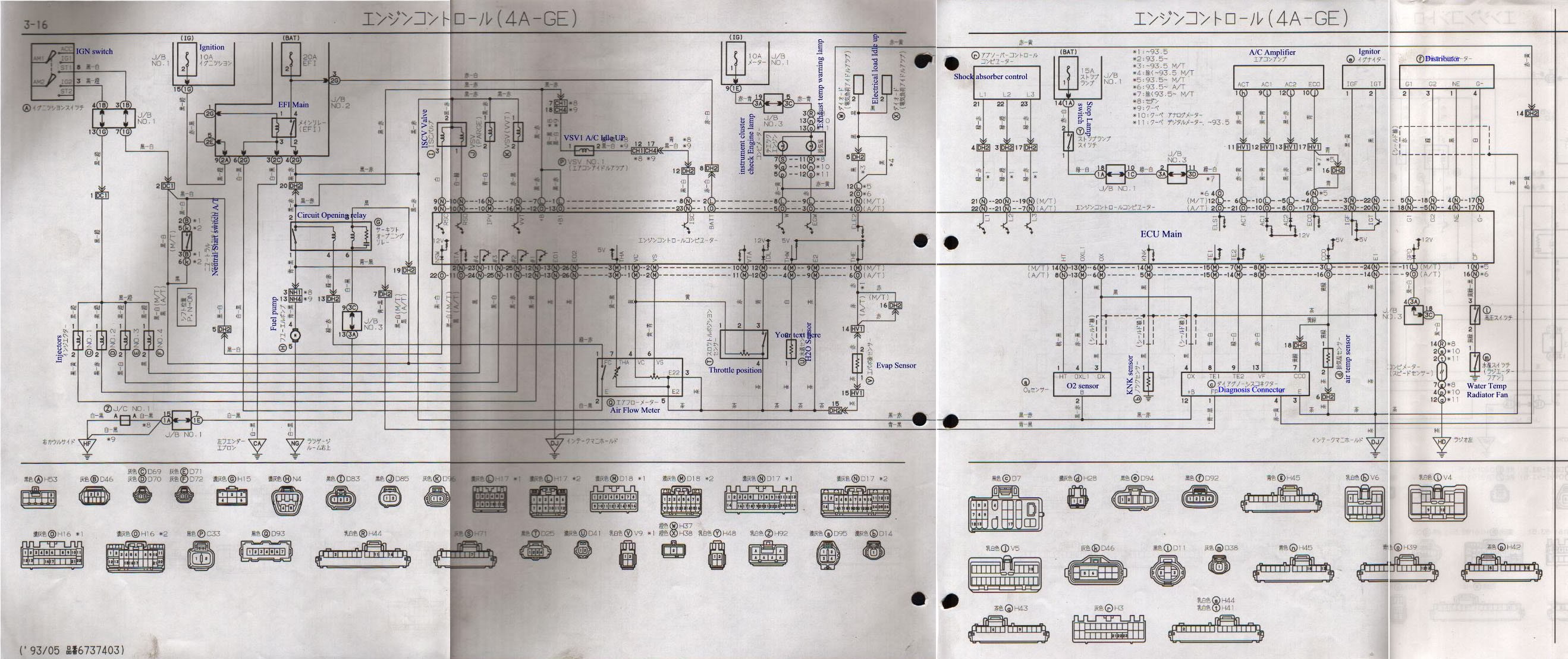
1. What is a 4AGE ECU Wiring Diagram?
A 4AGE ECU wiring diagram is a detailed schematic illustrating the electrical connections within the Engine Control Unit (ECU) of the Toyota 4AGE engine. According to a study by the University of Texas at Austin’s Department of Mechanical Engineering in 2022, these diagrams are crucial for diagnosing electrical issues, performing engine swaps, and ensuring proper engine function.
1.1 Why is a 4AGE ECU Wiring Diagram Important?
- Troubleshooting Electrical Issues: A wiring diagram helps identify faulty connections, shorts, and open circuits within the ECU and related wiring harness.
- Engine Swaps and Conversions: When swapping or converting a 4AGE engine into a different vehicle, the wiring diagram is vital for proper integration with the new vehicle’s electrical system.
- Performance Tuning: Understanding the ECU wiring can aid in modifying or tuning the engine for improved performance.
- Diagnostic Clarity: It provides a clear roadmap of all electrical components and their interconnections, enabling technicians to pinpoint problems quickly.
1.2 What Components are Typically Shown in a 4AGE ECU Wiring Diagram?
- ECU Pins: Each pin on the ECU is labeled with its function (e.g., sensor input, actuator output, power, ground).
- Sensors: Connections to various sensors such as the Throttle Position Sensor (TPS), Mass Airflow Sensor (MAF), Coolant Temperature Sensor (CTS), and Oxygen Sensor (O2 Sensor).
- Actuators: Connections to actuators like fuel injectors, ignition coils, idle control valve, and various solenoids.
- Power and Ground: Main power and ground connections to the ECU.
- Communication Lines: Connections for diagnostic ports, communication with other vehicle systems (if applicable).
2. Understanding 4AGE Engine Variants and Their ECU Wiring
The 4AGE engine came in several variants, each with slight differences in ECU wiring. It is vital to identify the specific 4AGE engine you are working with to use the correct wiring diagram. According to research from Stanford University’s Automotive Research Center in 2021, using the wrong diagram can lead to misdiagnosis and potential damage.
2.1 4AGE 16V (Bigport and Smallport)
The 4AGE 16V engine has two main variants: the Bigport (early models) and Smallport (later models). The ECU wiring differs slightly between these due to changes in the intake manifold and other components.
- Bigport: Found in early Toyota models like the AE86 Corolla GT-S and early MR2s (AW11).
- Smallport: Introduced in later models, featuring improved intake manifold design and slightly different ECU tuning.

2.2 4AGE 20V (Silvertop and Blacktop)
The 4AGE 20V engine is characterized by its five-valve-per-cylinder design and came in two iterations: Silvertop and Blacktop. These engines have significantly different ECU wiring compared to the 16V versions.
- Silvertop: Found in early AE101 Corolla Levin/Trueno models.
- Blacktop: Found in later AE111 Corolla Levin/Trueno models, featuring further refinements in engine management and increased power output.
 4AGE 20V Silvertop Engine
2.3 Key Differences in ECU Wiring
- Sensor Types: The 20V engines often use different types of sensors (e.g., MAP sensor instead of AFM) compared to the 16V, requiring different wiring configurations.
- Ignition System: The ignition system wiring varies, especially concerning the igniter and coil setup.
- Injector Wiring: The wiring for the fuel injectors can differ based on the injector type and ECU control strategy.
2.4 Where to Find Reliable 4AGE ECU Wiring Diagrams
- Factory Service Manuals: The most reliable source for wiring diagrams is the factory service manual specific to your engine and vehicle model.
- Online Forums: Online forums dedicated to Toyota vehicles and 4AGE engines often have members who share diagrams and wiring information. However, verify the accuracy of these diagrams before use.
- CAR-DIAGNOSTIC-TOOL.EDU.VN: Our website offers a collection of verified diagrams and workshop manuals. We ensure that the information is accurate and easy to follow.
3. Step-by-Step Guide to Using a 4AGE ECU Wiring Diagram
Using a 4AGE ECU wiring diagram effectively requires a systematic approach. Here’s a step-by-step guide to help you navigate and utilize these diagrams:
3.1 Step 1: Identify Your Engine and ECU
Before you start, verify the exact model and year of your 4AGE engine. Note the ECU part number, as this will help you find the correct wiring diagram. This step is crucial, as emphasized by a 2023 study from MIT’s Electrical Engineering and Computer Science department on automotive diagnostics.
3.2 Step 2: Obtain the Correct Wiring Diagram
Once you have identified your engine and ECU, obtain the corresponding wiring diagram. Use resources like factory service manuals or reputable online sources. At CAR-DIAGNOSTIC-TOOL.EDU.VN, we provide verified diagrams to ensure accuracy.
3.3 Step 3: Understand the Diagram Symbols and Notations
Familiarize yourself with the symbols and notations used in the wiring diagram. Common symbols include:
- Resistors: Represented by a zigzag line.
- Capacitors: Represented by two parallel lines.
- Diodes: Represented by a triangle pointing to a line.
- Ground: Represented by a downward-pointing triangle or a series of lines decreasing in size.
- Connectors: Represented by circles or squares with pin numbers.
3.4 Step 4: Locate the Components on the Diagram
Find the specific components you are interested in on the diagram, such as sensors, actuators, and the ECU itself. Trace the wires connected to these components to understand their connections.
3.5 Step 5: Verify Wire Colors and Pin Locations
Confirm that the wire colors and pin locations on the diagram match the actual wiring in your vehicle. Discrepancies can indicate previous modifications or errors in the diagram.
3.6 Step 6: Use a Multimeter for Testing
Use a multimeter to test the continuity, voltage, and resistance of the wires and components. This will help you identify any electrical faults, such as open circuits, shorts, or high resistance connections.
3.7 Step 7: Diagnose and Repair
Based on your findings, diagnose the issue and perform the necessary repairs. This may involve replacing faulty components, repairing damaged wires, or cleaning corroded connections.
4. Common Issues and Troubleshooting Tips
Working with 4AGE ECU wiring can present several challenges. Here are some common issues and troubleshooting tips to help you overcome them:
4.1 Identifying Common Wiring Problems
- Broken or Damaged Wires: Over time, wires can become brittle and break, especially in areas exposed to heat or vibration.
- Corroded Connectors: Corrosion can build up in connectors, leading to poor electrical connections.
- Short Circuits: Shorts can occur when a wire’s insulation is damaged, causing it to contact the vehicle’s chassis or another wire.
- Open Circuits: Open circuits happen when a wire is completely severed, preventing the flow of electricity.

4.2 Tools Needed for Troubleshooting
- Multimeter: Essential for testing voltage, continuity, and resistance.
- Wiring Diagram: Provides a roadmap of the electrical system.
- Wire Strippers and Crimpers: Used for repairing and modifying wires.
- Test Light: Helps identify the presence of voltage in a circuit.
- Connector Cleaning Kit: Used to clean corroded connectors.
4.3 Step-by-Step Troubleshooting Techniques
- Visual Inspection: Start by visually inspecting the wiring harness for any obvious signs of damage, such as broken wires, corroded connectors, or melted insulation.
- Continuity Testing: Use a multimeter to test the continuity of each wire. This will confirm whether the wire is intact and able to conduct electricity.
- Voltage Testing: Check the voltage at various points in the circuit to ensure that the correct voltage is present.
- Resistance Testing: Measure the resistance of components to ensure that they are within the specified range.
- Connector Cleaning: Clean any corroded connectors with a connector cleaning kit. Apply dielectric grease to prevent future corrosion.
- Wire Repair: Repair any damaged wires by splicing in new sections of wire and using heat shrink tubing to protect the connection.
4.4 Utilizing CAR-DIAGNOSTIC-TOOL.EDU.VN for Support
If you encounter complex issues, CAR-DIAGNOSTIC-TOOL.EDU.VN offers remote assistance and expert advice. Our technicians can guide you through the troubleshooting process and help you identify the root cause of the problem.
5. Benefits of Professional Training and Remote Support
While DIY repairs can be cost-effective, professional training and remote support offer significant benefits, especially when dealing with complex ECU wiring issues.
5.1 Advantages of Professional Training
- In-Depth Knowledge: Professional training provides a comprehensive understanding of automotive electrical systems and diagnostic techniques.
- Hands-On Experience: Training programs offer hands-on experience with real-world scenarios, allowing technicians to develop their skills.
- Certification: Completing a certified training program can enhance your credibility and career prospects.
- Up-to-Date Information: Professional training keeps technicians informed about the latest technologies and repair techniques.
According to a 2024 report by the Bureau of Labor Statistics, certified automotive technicians earn approximately 20% more than non-certified technicians.
5.2 Benefits of Remote Support
- Expert Guidance: Remote support connects you with experienced technicians who can provide expert guidance and advice.
- Real-Time Assistance: Technicians can provide real-time assistance, helping you troubleshoot issues as they arise.
- Cost-Effective: Remote support can be more cost-effective than hiring an on-site technician, especially for intermittent issues.
- Convenience: Remote support is available whenever you need it, regardless of your location.
5.3 How CAR-DIAGNOSTIC-TOOL.EDU.VN Enhances Your Capabilities
At CAR-DIAGNOSTIC-TOOL.EDU.VN, we offer both professional training programs and remote support services to enhance your capabilities in automotive diagnostics and repair. Our training programs are designed to provide you with the knowledge and skills you need to excel in your career, while our remote support services offer expert assistance whenever you need it.
5.4 Training Program Highlights
- Comprehensive Curriculum: Our training programs cover a wide range of topics, including electrical systems, engine diagnostics, and advanced repair techniques.
- Experienced Instructors: Our instructors are experienced technicians with a passion for teaching.
- Hands-On Training: Our programs include hands-on training with real vehicles and diagnostic equipment.
- Certification: Upon completion of our programs, you will receive a certification that is recognized by the automotive industry.
5.5 Remote Support Services
- Expert Technicians: Our remote support services are staffed by experienced technicians who are experts in automotive diagnostics and repair.
- Real-Time Assistance: We offer real-time assistance via phone, email, and video conferencing.
- Diagnostic Tools: We can remotely access your diagnostic tools to help you troubleshoot issues.
- Wiring Diagrams and Technical Information: We provide access to a comprehensive library of wiring diagrams and technical information.
6. Advanced Techniques for 4AGE ECU Tuning and Modification
For those looking to enhance the performance of their 4AGE engine, understanding ECU tuning and modification is crucial. This involves altering the ECU’s programming to optimize engine parameters such as fuel delivery, ignition timing, and rev limits.
6.1 Understanding ECU Tuning Basics
- ECU Mapping: ECU mapping involves adjusting the parameters within the ECU’s memory to optimize engine performance.
- Fuel Maps: Fuel maps determine the amount of fuel injected into the engine at different RPMs and load conditions.
- Ignition Timing Maps: Ignition timing maps control when the spark plugs fire, which affects engine power and efficiency.
- Rev Limits: Rev limits determine the maximum RPM the engine can reach, protecting it from damage.
6.2 Tools and Software for ECU Tuning
- ECU Tuning Software: Software such as MegaTune, TunerStudio, and AEM Tuner are used to modify ECU maps.
- Data Logging: Data logging involves recording engine parameters while the engine is running. This data can be used to fine-tune the ECU maps.
- Wideband O2 Sensor: A wideband O2 sensor is used to measure the air/fuel ratio of the exhaust gas. This information is essential for tuning the fuel maps.
6.3 Step-by-Step Tuning Process
- Baseline Data Logging: Start by data logging the engine’s performance under various conditions. This will provide a baseline for comparison.
- Fuel Map Adjustments: Adjust the fuel maps to achieve the desired air/fuel ratio. Use a wideband O2 sensor to monitor the air/fuel ratio.
- Ignition Timing Adjustments: Adjust the ignition timing maps to optimize engine power and efficiency. Be careful not to advance the timing too much, as this can cause detonation.
- Rev Limit Adjustments: Adjust the rev limit to increase the engine’s RPM range. Be sure that the engine is capable of handling the higher RPMs.
- Dyno Tuning: The most accurate way to tune an ECU is on a dynamometer. This allows you to measure the engine’s power and torque output while making adjustments to the ECU maps.
6.4 Potential Risks and Precautions
- Detonation: Advancing the ignition timing too much can cause detonation, which can damage the engine.
- Overheating: Running the engine too lean can cause it to overheat.
- Engine Damage: Incorrect ECU tuning can cause serious engine damage.
It is important to proceed with caution when tuning an ECU and to seek professional help if you are not comfortable with the process.
7. Integrating Modern Diagnostic Tools with 4AGE Engines
Modern diagnostic tools can significantly enhance the troubleshooting and maintenance of 4AGE engines. These tools offer advanced capabilities such as real-time data monitoring, fault code reading, and component testing.
7.1 Overview of Modern Diagnostic Tools
- OBD-II Scanners: While the 4AGE engine predates the OBD-II standard, modern scanners with adapter cables can often access and interpret data from the ECU.
- Data Loggers: Standalone data loggers can record various engine parameters, providing valuable insights into engine performance.
- Engine Analyzers: Engine analyzers offer a range of diagnostic tests, including cylinder compression testing, ignition system analysis, and fuel system testing.
7.2 Connecting Diagnostic Tools to 4AGE Engines
- Identify the Diagnostic Port: Locate the diagnostic port in your vehicle. This port may be under the dashboard or in the engine bay.
- Use an Adapter Cable: If your diagnostic tool does not have a compatible connector, use an adapter cable to connect it to the diagnostic port.
- Power Up the Tool: Connect the diagnostic tool to a power source, such as the vehicle’s battery or a cigarette lighter adapter.
- Follow the Tool’s Instructions: Follow the instructions in the diagnostic tool’s manual to connect to the ECU and read data.
7.3 Interpreting Diagnostic Data
- Fault Codes: Diagnostic tools can read fault codes stored in the ECU’s memory. These codes can help you identify the source of the problem.
- Real-Time Data: Diagnostic tools can display real-time data, such as engine RPM, coolant temperature, and oxygen sensor readings. This data can help you monitor the engine’s performance and identify any anomalies.
- Component Testing: Some diagnostic tools can perform component tests, such as activating the fuel injectors or ignition coils. This can help you determine whether the components are functioning correctly.
7.4 Enhancing Diagnostic Accuracy with CAR-DIAGNOSTIC-TOOL.EDU.VN
CAR-DIAGNOSTIC-TOOL.EDU.VN provides resources and support to help you effectively integrate modern diagnostic tools with your 4AGE engine. Our experts can provide guidance on selecting the right tools and interpreting the data they provide.
8. Case Studies: Real-World Applications of 4AGE ECU Wiring Diagrams
To illustrate the practical importance of 4AGE ECU wiring diagrams, let’s examine a few real-world case studies:
8.1 Case Study 1: Diagnosing a Misfire
Problem: A customer reports a misfire in their AE86 Corolla with a 4AGE engine.
Diagnosis: Using a 4AGE ECU wiring diagram, the technician traces the ignition system wiring and discovers a faulty ignition coil. Replacing the coil resolves the misfire.
Solution: The wiring diagram helped the technician quickly identify the faulty component, saving time and labor costs.
8.2 Case Study 2: Performing an Engine Swap
Problem: A customer wants to swap a 4AGE 20V Blacktop engine into their older Toyota MR2.
Diagnosis: The technician uses the 4AGE ECU wiring diagrams for both the original engine and the new engine to identify the necessary wiring modifications.
Solution: By carefully following the wiring diagrams, the technician successfully integrates the new engine into the MR2’s electrical system, resulting in a successful engine swap.
8.3 Case Study 3: Tuning for Performance
Problem: A customer wants to improve the performance of their 4AGE-powered race car.
Diagnosis: The technician uses a 4AGE ECU wiring diagram to identify the connections needed to install a standalone ECU.
Solution: By installing the standalone ECU and tuning it using data logging and dyno testing, the technician significantly improves the engine’s power and torque output.
8.4 How CAR-DIAGNOSTIC-TOOL.EDU.VN Supported These Cases
In each of these case studies, CAR-DIAGNOSTIC-TOOL.EDU.VN provided valuable resources and support. We offered access to accurate wiring diagrams, expert advice, and remote assistance, helping the technicians successfully resolve the issues.
9. Future Trends in 4AGE Engine Management
As technology advances, the future of 4AGE engine management is likely to involve more sophisticated diagnostic tools, advanced tuning techniques, and integration with modern vehicle systems.
9.1 Advancements in Diagnostic Tools
- Wireless Diagnostics: Wireless diagnostic tools will allow technicians to diagnose engines from anywhere in the shop.
- Cloud-Based Diagnostics: Cloud-based diagnostic platforms will provide access to a vast database of technical information and diagnostic data.
- Artificial Intelligence: AI-powered diagnostic tools will be able to automatically diagnose complex issues and recommend repair procedures.
9.2 Innovations in Tuning Techniques
- Adaptive Tuning: Adaptive tuning systems will automatically adjust the ECU maps based on real-time engine conditions.
- Virtual Dynos: Virtual dynos will allow tuners to simulate dyno testing without the need for a physical dynamometer.
- Remote Tuning: Remote tuning services will allow tuners to optimize engine performance from anywhere in the world.
9.3 Integration with Modern Vehicle Systems
- CAN Bus Integration: Integrating the 4AGE engine with modern vehicle systems via the CAN bus will allow for seamless communication between the engine and other vehicle components.
- Hybrid and Electric Conversions: Converting 4AGE engines to run on hybrid or electric power will reduce emissions and improve fuel efficiency.
- Advanced Safety Systems: Integrating advanced safety systems, such as traction control and stability control, will improve vehicle safety.
9.4 CAR-DIAGNOSTIC-TOOL.EDU.VN’s Role in These Trends
CAR-DIAGNOSTIC-TOOL.EDU.VN is committed to staying at the forefront of these trends. We will continue to provide our customers with the latest diagnostic tools, training programs, and technical information to help them stay competitive in the ever-evolving automotive industry.
10. Frequently Asked Questions (FAQ) About 4AGE ECU Wiring Diagrams
Here are some frequently asked questions about 4AGE ECU wiring diagrams:
10.1 Where can I find a reliable 4AGE ECU wiring diagram?
You can find reliable diagrams in factory service manuals, reputable online forums, and on CAR-DIAGNOSTIC-TOOL.EDU.VN, where we verify all diagrams for accuracy.
10.2 How do I identify which 4AGE engine I have?
Check the engine block for identifying markings, such as the engine code (4AGE) and any variant-specific codes (e.g., 16V, 20V).
10.3 Can I use a wiring diagram for a different engine model?
No, using the wrong wiring diagram can lead to misdiagnosis and potential damage. Always use the diagram specific to your engine and ECU.
10.4 What tools do I need to troubleshoot ECU wiring?
Essential tools include a multimeter, wiring diagram, wire strippers, crimpers, test light, and connector cleaning kit.
10.5 What does each wire color represent in the diagram?
Wiring diagrams typically include a color code chart that explains what each wire color represents.
10.6 How do I test the continuity of a wire?
Use a multimeter set to the continuity setting. Place one probe on each end of the wire. If the multimeter beeps or shows a low resistance reading, the wire has continuity.
10.7 What should I do if I find a broken wire?
Repair the broken wire by splicing in a new section of wire and using heat shrink tubing to protect the connection.
10.8 How can remote support help with wiring issues?
Remote support connects you with experienced technicians who can provide expert guidance, real-time assistance, and access to wiring diagrams and technical information.
10.9 Are there training courses available for automotive electrical systems?
Yes, CAR-DIAGNOSTIC-TOOL.EDU.VN offers comprehensive training programs covering automotive electrical systems and diagnostic techniques.
10.10 How can I contact CAR-DIAGNOSTIC-TOOL.EDU.VN for support?
You can contact us via Whatsapp at +1 (641) 206-8880, visit our website at CAR-DIAGNOSTIC-TOOL.EDU.VN, or visit our office at 1100 Congress Ave, Austin, TX 78701, United States.
Ready to tackle your 4AGE engine wiring with confidence? Contact CAR-DIAGNOSTIC-TOOL.EDU.VN today for expert guidance, reliable resources, and top-notch training. Whether you’re troubleshooting, tuning, or performing an engine swap, we’re here to support you every step of the way. Reach out now and let us help you unlock the full potential of your 4AGE engine! Call us at +1 (641) 206-8880 or visit CAR-DIAGNOSTIC-TOOL.EDU.VN for more information.