The Can/bus Ecu is a cornerstone of modern automotive systems, facilitating communication between electronic components and enabling advanced diagnostics. CAR-DIAGNOSTIC-TOOL.EDU.VN provides comprehensive tools, detailed repair guides, and expert technical assistance to help you master CAN/Bus ECU diagnostics and repair. Our resources empower technicians with up-to-date information and remote support, ensuring efficient and accurate vehicle servicing, along with training programs to elevate your skills and knowledge base.
Contents
- 1. Understanding the Basics of CAN/Bus ECU Systems
- 1.1. The Role of CAN/Bus in Vehicle Communication
- 1.2. Physical Components of a CAN/Bus System
- 1.3. What is an ECU and Its Functions?
- 1.4. Key Components of an ECU
- 1.5. Different CAN/Bus Variants
- 1.6. Other Automotive Networks
- 2. Unveiling the Benefits of CAN/Bus Systems
- 2.1. Simplicity and Cost-Effectiveness
- 2.2. Easy Access for Centralized Diagnostics
- 2.3. Robustness Against Electric Disturbances
- 2.4. Efficiency in Data Transmission
- 3. A Brief History and Future Trends of CAN/Bus
- 3.1. Historical Development of CAN/Bus
- 3.2. Current Applications of CAN/Bus
- 3.3. Future Trends in CAN/Bus Technology
- 4. Exploring the CAN/Bus Physical and Data Link Layers
- 4.1. The OSI Model and CAN/Bus
- 4.2. Physical Layer Specifications (ISO 11898-2)
- 4.3. Data Link Layer Specifications (ISO 11898-1)
- 5. Decoding the CAN Frame Structure
- 5.1. Components of a CAN Data Frame
- 5.2. Types of CAN Frames
- 5.3. CAN/Bus Error Handling
- 6. Understanding Higher-Layer CAN Protocols
- 6.1. Overview of Common Automotive/Industrial CAN Protocols
- 6.2. Analogy: CAN/Bus vs. Higher-Layer Protocols
- 6.3. Other Common CAN Protocols
- 7. Practical Guide: How to Log CAN/Bus Data
- 7.1. Selecting the Right Hardware
- 7.2. Identifying the Correct Adapter Cable
- 7.2.1. Adapter Tips Based on Use Case
- 7.3. Configuring and Connecting Your Device
- 7.4. Reviewing Raw CAN Data
- 8. Decoding Raw CAN Data: Converting to Physical Values
- 8.1. Understanding CAN Signal Extraction
- 8.2. Obtaining the Relevant DBC File
- 8.3. Utilizing Software/API Tools
- 9. Example Use Cases for Logging CAN Data
- 10. Level Up Your Expertise with CAR-DIAGNOSTIC-TOOL.EDU.VN
- 10.1. Overcome Your Challenges
- 10.2. Solutions Tailored to Your Needs
- 10.3. Transform Your Approach
- 10.4. Take the Next Step
- FAQ: Your Questions About CAN/Bus ECU Answered
- 1. What is a CAN/Bus ECU?
- 2. How does a CAN/Bus system improve vehicle diagnostics?
- 3. What are the main components of an ECU?
- 4. What is a DBC file, and why is it important?
- 5. What is the difference between CAN/Bus and higher-layer protocols?
- 6. How can I log CAN/Bus data from a vehicle?
- 7. What are some common applications of CAN/Bus data logging?
- 8. What tools does CAR-DIAGNOSTIC-TOOL.EDU.VN offer for CAN/Bus ECU diagnostics?
- 9. How can remote technical support from CAR-DIAGNOSTIC-TOOL.EDU.VN help me with CAN/Bus issues?
- 10. What kind of training programs does CAR-DIAGNOSTIC-TOOL.EDU.VN offer to enhance my CAN/Bus diagnostic skills?
1. Understanding the Basics of CAN/Bus ECU Systems
What exactly is a CAN/Bus ECU, and why is it so crucial in modern vehicles? A CAN/Bus ECU (Controller Area Network/Bus Electronic Control Unit) serves as the central nervous system of a vehicle, facilitating communication between various electronic components without needing a central host computer. According to Bosch, the inventor of the CAN protocol, this system allows ECUs to share data efficiently and reliably, improving overall vehicle performance and safety.
1.1. The Role of CAN/Bus in Vehicle Communication
The CAN/Bus system allows various ECUs, such as the engine control unit, transmission control unit, and anti-lock braking system, to communicate with each other. This network ensures that data sensed by one part of the vehicle can be shared with other parts, optimizing performance and coordination. For instance, information from the brakes can be rapidly shared with the engine to enhance safety and responsiveness.
1.2. Physical Components of a CAN/Bus System
The physical layer of a CAN/Bus system consists of a two-wire bus, typically a twisted pair, known as CAN High and CAN Low. These wires are often color-coded with CAN High being yellow (like the sun) and CAN Low being green (like the grass). The physical layer is standardized by ISO 11898-2, defining cable types, electrical signal levels, and impedance.
1.3. What is an ECU and Its Functions?
Electronic Control Units (ECUs) are integral components that manage specific functions within a vehicle. A modern car can have over 70 ECUs, each dedicated to controlling aspects like the engine, transmission, brakes, steering, and climate control. Each ECU can broadcast data, such as sensor readings, across the CAN/Bus network.
1.4. Key Components of an ECU
Each ECU typically includes three key components:
- Microcontroller (MCU): The brain of the ECU, responsible for interpreting incoming CAN messages and determining which messages to transmit.
- CAN Controller: Manages communication according to the CAN protocol, handling message encoding, error detection, and arbitration.
- CAN Transceiver: Connects the CAN controller to the physical CAN wires, converting data into differential signals for the CAN/Bus system.
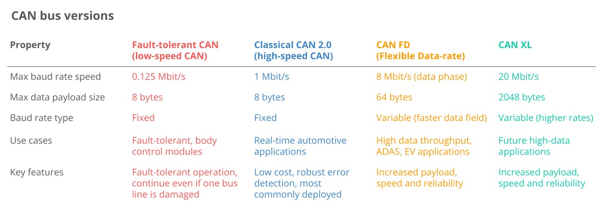
1.5. Different CAN/Bus Variants
Several CAN/Bus variants exist, each tailored for specific needs:
- Low-Speed CAN: Also known as fault-tolerant CAN, it’s a cost-effective option for applications where fault tolerance is critical.
- High-Speed CAN: The most common variant in automotive and machinery, offering a balance of speed and reliability.
- CAN FD (Flexible Data-Rate): Provides longer payloads and faster speeds, enhancing data throughput. More details can be found at CAR-DIAGNOSTIC-TOOL.EDU.VN in our advanced diagnostics section.
- CAN XL: The latest iteration, offering even longer payloads and faster speeds to bridge the gap between CAN and Automotive Ethernet.
1.6. Other Automotive Networks
Besides CAN/Bus, other networks are used in vehicles:
- LIN (Local Interconnect Network) Bus: A lower-cost alternative to CAN/Bus for less critical functions like air conditioning and door controls.
- FlexRay: Offers higher speeds and fault tolerance but is more costly, standardized by ISO 17458-1 and ISO 17458-5.
- Automotive Ethernet: Increasingly used for high-bandwidth applications like ADAS (Advanced Driver Assistance Systems) and infotainment.
 Classical CAN FD XL Variants canbus
2. Unveiling the Benefits of CAN/Bus Systems
What makes CAN/Bus systems so indispensable in modern automotive technology? CAN/Bus systems offer numerous advantages that make them crucial in modern vehicles. These benefits include simplicity, cost-effectiveness, easy access for diagnostics, robustness against interference, and efficiency in data transmission.
2.1. Simplicity and Cost-Effectiveness
CAN/Bus systems reduce the complexity and cost associated with traditional wiring. By using a single CAN/Bus system for communication, the number of wires is reduced, which decreases weight and minimizes potential errors.
- Reduced Wire Complexity: Point-to-point wiring systems require dedicated wires between each node, increasing costs and reducing flexibility.
- Weight Reduction: CAN/Bus systems can reduce the weight of a vehicle’s wiring harness by up to 20 kg, improving fuel efficiency, according to Connector Supplier.
- Scale: The widespread adoption of CAN/Bus reduces the cost of controllers, transceivers, and data acquisition hardware.
2.2. Easy Access for Centralized Diagnostics
CAN/Bus systems provide a single point of entry for communicating with all ECUs, enabling centralized diagnostics, data logging, and configuration.
- Centralized Diagnostics: Access 100% of the traffic by connecting an interface anywhere on the CAN/Bus, simplifying diagnostics.
- Silent CAN Logging: Critical for diagnostics, CAN/Bus data logging can be performed in silent mode without affecting the network. CAR-DIAGNOSTIC-TOOL.EDU.VN offers extensive guides on silent CAN logging techniques.
- ECU Flashing: Update any ECU on the network by transmitting firmware or configuration updates via CAN frames using protocols like UDS or CCP/XCP.
- Standardization: Standardized higher-layer protocols enhance interoperability of hardware and software tools across manufacturers.
2.3. Robustness Against Electric Disturbances
CAN/Bus systems are designed to be highly robust against electrical disturbances and electromagnetic interference, making them ideal for safety-critical applications.
- Differential Signaling: EMI affects both lines equally, making the differential signal robust.
- Error Handling: CAN/Bus ensures data integrity through error detection, including bit errors, stuff errors, CRC errors, form errors, and ACK errors.
- Confinement: Nodes track errors and disconnect from the bus if thresholds are exceeded, preventing bus jamming.
2.4. Efficiency in Data Transmission
CAN/Bus systems prioritize frames by ID, ensuring that high-priority data gets immediate bus access without interrupting other frames.
- Arbitration: The frame with the lowest CAN ID (highest priority) wins when multiple nodes transmit data, avoiding collisions.
- Utilization: Arbitration ensures that the CAN/Bus bandwidth is well-utilized, effectively filling gaps between critical messages with lower-priority messages.
- Speed: Provides sufficient speed for most automotive and industrial applications today.
3. A Brief History and Future Trends of CAN/Bus
How did CAN/Bus evolve to become the backbone of automotive communication, and what does the future hold? The CAN/Bus protocol was developed by Bosch in 1986 to replace complex point-to-point wiring in vehicles. It has since evolved through several key milestones, becoming a standard in various industries.
3.1. Historical Development of CAN/Bus
- Pre CAN: Car ECUs relied on complex point-to-point wiring.
- 1986: Bosch developed the CAN protocol.
- 1991: Bosch published CAN 2.0 (CAN 2.0A: 11 bit, 2.0B: 29 bit).
- 1993: CAN is adopted as an international standard (ISO 11898).
- 2003: ISO 11898 becomes a standard series.
- 2012: Bosch released CAN FD 1.0 (flexible data rate).
- 2015: The CAN FD protocol is standardized (ISO 11898-1).
- 2016: The physical CAN layer for data-rates up to 5 Mbit/s standardized in ISO 11898-2.
- 2018: CiA starts development of CAN XL.
- 2024: CAN XL standardized (ISO 11898-1:2024, 11898-2:2024).
3.2. Current Applications of CAN/Bus
Today, CAN/Bus is standard in automotives (cars, trucks, buses, tractors), ships, planes, EV batteries, and machinery.
3.3. Future Trends in CAN/Bus Technology
Looking ahead, the CAN/Bus protocol will remain relevant, influenced by major trends:
- Need for Speed: Demand for higher data rates may drive transition towards CAN FD, CAN XL, or Automotive Ethernet.
- Connected Vehicles: Rise of cloud computing and vehicle telematics may enable predictive maintenance and remote troubleshooting but also cybersecurity risks.
- Open vs. Closed: A push towards ‘Open Source’ and Right to Repair may face off vs. OEM-driven demand for keeping data proprietary to offer subscription-based microservices.
4. Exploring the CAN/Bus Physical and Data Link Layers
What are the technical specifications that govern CAN/Bus communication? In technical terms, the Controller Area Network is described by a data link layer and physical layer. For high-speed CAN, ISO 11898-1 describes the data link layer, while ISO 11898-2 describes the physical layer.
4.1. The OSI Model and CAN/Bus
In the context of a 7 layer OSI model, CAN represents the two lowest layers.
4.2. Physical Layer Specifications (ISO 11898-2)
The CAN/Bus physical layer defines cable types, electrical signal levels, node requirements, and cable impedance.
- Baud Rate: Nodes must be connected via a two-wire bus with baud rates up to 1 Mbit/s (Classical CAN) or 8 Mbit/s (CAN FD).
- Cable Length: Maximal CAN cable lengths should be between 500 meters (125 kbit/s) and 40 meters (1 Mbit/s).
- Termination: The CAN/Bus must be terminated using a 120 Ohm termination resistor at each end of the bus.
4.3. Data Link Layer Specifications (ISO 11898-1)
The CAN/Bus data link layer defines CAN frame formats, error handling, and data transmission to ensure data integrity.
- Frame Formats: Four types (data frames, remote frames, error frames, overload frames) and 11-bit/29-bit identifiers.
- Error Handling: Methods for detecting/handling CAN errors including CRC, acknowledgement slots, and error counters.
- Arbitration: Non-destructive bitwise arbitration helps manage CAN/Bus access and avoid collisions via ID-based priority.
5. Decoding the CAN Frame Structure
What is the structure of a CAN frame, and how does it facilitate data transmission? Communication over the CAN/Bus is done via CAN frames. A standard CAN data frame with an 11-bit identifier (CAN 2.0A) is commonly used, while the extended 29-bit identifier frame (CAN 2.0B) is used in protocols like J1939.
5.1. Components of a CAN Data Frame
- SOF (Start of Frame): A ‘dominant 0’ to indicate a node intends to transmit.
- ID: The frame identifier, with lower values having higher priority.
- RTR (Remote Transmission Request): Indicates whether a node sends data or requests data.
- Control: Contains the Identifier Extension Bit (IDE) and the 4-bit Data Length Code (DLC).
- Data: Contains the data bytes or payload, including CAN signals.
- CRC (Cyclic Redundancy Check): Ensures data integrity.
- ACK (Acknowledge): Indicates if the node has acknowledged and received the data correctly.
- EOF (End of Frame): Marks the end of the CAN frame.
5.2. Types of CAN Frames
- Data Frame: Carries data from a sender CAN node to one or more receiver nodes.
- Error Frame: Indicates the detection of a communication error.
- Remote Frame: Requests specific data from a CAN node.
- Overload Frame: Provides additional delay between CAN frames.
5.3. CAN/Bus Error Handling
If an erroneous CAN frame is transmitted, CAN nodes automatically detect it and take action. CAN nodes track error counters and change state (active, passive, bus off) depending on their counters.
6. Understanding Higher-Layer CAN Protocols
Why are higher-layer protocols necessary for CAN/Bus communication? As a lower-layer protocol, CAN provides a basis for communication but doesn’t specify how to handle messages larger than 8 bytes or decode raw data. Higher-layer protocols detail how data is communicated between CAN nodes in a given network.
6.1. Overview of Common Automotive/Industrial CAN Protocols
- OBD2 (On-Board Diagnostics): Used for diagnostics, maintenance, and emissions tests in cars and trucks, specifying diagnostic trouble codes (DTCs) and real-time data.
- UDS (Unified Diagnostic Services): A communication protocol used in automotive ECUs for diagnostics, firmware updates, and routine testing.
- CCP/XCP (CAN Calibration Protocol/Universal Measurement and Calibration Protocol): Enables read/write ECU access for calibration, measurement, and flashing.
- CANopen: Widely used in embedded control applications and industrial automation for interoperability between CAN nodes.
- SAE J1939: Used in heavy-duty vehicles, identifying parameters like speed with suspect parameter numbers (SPN) grouped by parameter group numbers (PGN).
- NMEA 2000: Used in the maritime industry for connecting engines, instruments, and sensors on boats, based on CAN and closely linked to J1939.
- ISOBUS (ISO 11783): Used in agriculture and forestry machinery, enabling plug & play integration between vehicles and implements across brands, closely linked to J1939.
6.2. Analogy: CAN/Bus vs. Higher-Layer Protocols
Think of people communicating: CAN/Bus defines the physical requirements (like vocal chords) and basic building blocks (like letters and grammar), while higher-layer protocols reflect different languages (like German or English).
- Always a Higher-Layer Protocol: In practical applications, there is always a higher-layer protocol in use.
- Thousands of Protocols Exist: Like languages, thousands of higher-layer protocols exist, including manufacturer/application-specific protocols.
- Recording vs. Understanding Data: A CAN/Bus data logger can record any CAN-based communication, but to interpret the information, you need to understand the higher-layer protocol.
- Multiple Protocols: Your car uses a CAN-based higher-layer protocol for communicating data between ECUs, as well as standardized protocols like OBD2 or UDS for diagnostics.
- Interoperability: Standardized higher-layer protocols provide interoperability across applications and related devices.
6.3. Other Common CAN Protocols
- ARINC: Commonly used in the aerospace industry.
- UAVCAN: Open source and lightweight protocol often used in drones, aerospace, and robotics.
- DeviceNet: Used in industrial automation and manufacturing.
- SafetyBUS p: Used in safety-critical industrial automation.
- MilCAN: Designed for use in military vehicles and harsh environments.
- HVAC CAN: Designed for use in Heating, Ventilation, and Air Conditioning systems.
7. Practical Guide: How to Log CAN/Bus Data
What steps are involved in effectively logging CAN/Bus data for analysis? Logging CAN/Bus data involves selecting the right hardware, identifying the appropriate adapter cable, configuring the device, and reviewing the raw CAN data.
7.1. Selecting the Right Hardware
Decide how you wish to collect the CAN data. CAR-DIAGNOSTIC-TOOL.EDU.VN offers a range of CAN loggers and interfaces to suit various needs.
7.2. Identifying the Correct Adapter Cable
Determine the adapter needed based on the application:
- OBD2 Adapter: Used in most cars for requesting OBD2/UDS data and accessing proprietary CAN data.
- J1939 Adapter: Used in heavy-duty vehicles for accessing raw CAN data (J1939 protocol).
- M12 Adapter: Used in maritime vessels and some industrial machinery for recording raw CAN data (NMEA 2000 or CANopen).
- Contactless CAN Reader: A universal option that uses induction to read data directly from the CAN high/low wiring harness.
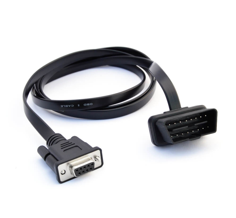 On Board Diagnostic OBD2 Connector Adapter
7.2.1. Adapter Tips Based on Use Case
- Cars: The OBD2 adapter is typically used for logging data.
- Heavy-Duty: The J1939 adapter is most common.
- Maritime: The M12 connector is most often encountered.
- Industrial Machinery: You can often use the M12 adapter.
- Agriculture: Use the J1939 adapter.
- Labs & Test Benches: Use a generic adapter that provides open-wire connections.
- Universal: The Contactless CAN reader can be used.
Regardless of the application, a Contactless CAN reader can be used to access the physical CAN bus wiring harness.
7.3. Configuring and Connecting Your Device
Before connecting your device:
- Baud-Rate: Your device baud rate must match the CAN/Bus.
- Requests: Configure your device to transmit the relevant request messages for on-request data like OBD2/UDS.
7.4. Reviewing Raw CAN Data
Once you have recorded data, review the log file. Raw CAN/Bus data is not human-readable and needs to be decoded.
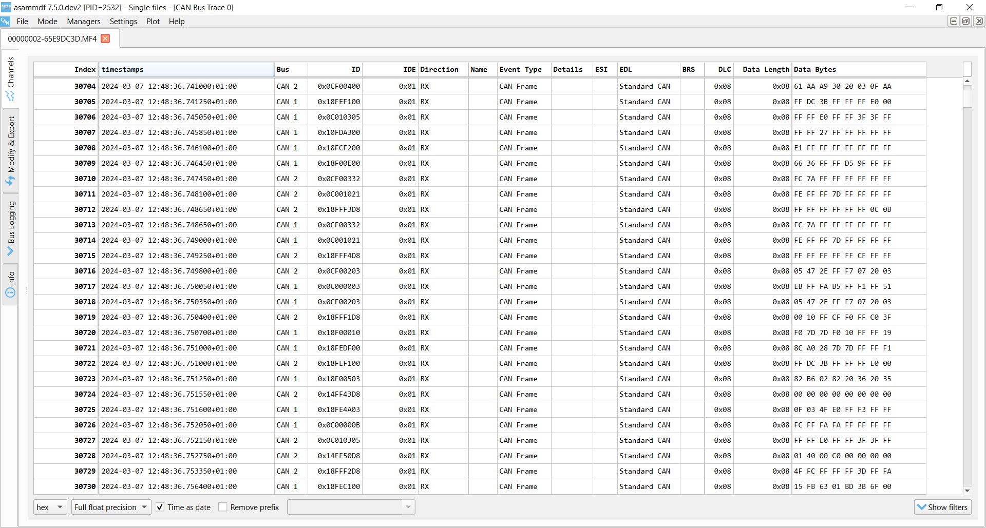 Raw CAN bus data example asammdf J1939
8. Decoding Raw CAN Data: Converting to Physical Values
How do you transform raw CAN data into meaningful, scaled engineering values? Decoding raw CAN data requires converting CAN frames into scaled engineering values or physical values, such as km/h or degrees. This process involves a DBC file and specialized software tools.
8.1. Understanding CAN Signal Extraction
Each CAN frame contains CAN signals in the data payload. Extracting the physical value of a CAN signal requires:
- Byte Order: Whether data is encoded in Intel or Motorola format.
- Bit Start: The starting bit of the signal.
- Bit Length: The length of the signal in bits.
- Offset: Value to offset the signal value by.
- Scale: Value to multiply the signal value by.
8.2. Obtaining the Relevant DBC File
A CAN DBC file (CAN database) is a text file that contains information for decoding raw CAN data. Generally, DBC files are application-specific and proprietary, often available only to the Original Equipment Manufacturer (OEM).
8.3. Utilizing Software/API Tools
Use a software/API tool that supports your log file format and DBC files. Software options depend on the use case:
- asammdf GUI: Useful for ad hoc analysis, diagnostics, and export.
- Grafana Dashboards: Enable data visualization, reporting, and insight sharing.
- MATLAB/Python: Enable statistical analysis and big data processing.
9. Example Use Cases for Logging CAN Data
What are some common applications for CAN/Bus data logging? There are several common use cases for recording CAN/Bus data:
- Logging/Streaming Data from Cars: OBD2 data can be used to reduce fuel costs, improve driving, and test prototype parts.
- Heavy-Duty Fleet Telematics: J1939 data from trucks, buses, and tractors can be used in fleet management to reduce costs and improve safety.
- Predictive Maintenance: Monitor vehicles and machinery via IoT CAN loggers to predict and avoid breakdowns.
- Vehicle/Machine Blackbox: A CAN logger can serve as a ‘blackbox’ for vehicles or equipment, providing data for disputes or diagnostics.
10. Level Up Your Expertise with CAR-DIAGNOSTIC-TOOL.EDU.VN
Are you ready to take your diagnostic skills to the next level? At CAR-DIAGNOSTIC-TOOL.EDU.VN, we understand the challenges technicians face: the demand for physical strength, constant exposure to harsh chemicals, and the need to stay updated with ever-evolving automotive technology. Our mission is to provide you with the tools, knowledge, and support necessary to excel in your profession.
10.1. Overcome Your Challenges
Our services are designed to address your specific challenges:
- Enhance Efficiency: Reduce repair times through accurate diagnostics.
- Detailed Guidance: Access step-by-step repair guides that are easy to understand.
- Increase Accuracy: Improve precision and safety in your work processes.
- Remote Support: Get technical assistance from remote experts for complex issues.
- Continuous Learning: Upgrade your skills and stay current with new technologies.
- Cost Savings: Reduce repair and maintenance expenses for your customers.
- Revenue Growth: Boost your garage’s income and profitability.
- Reputation: Enhance your garage’s reputation and service quality.
10.2. Solutions Tailored to Your Needs
We offer a comprehensive suite of services to meet your needs:
- Advanced Diagnostic Tools: Cutting-edge equipment for precise and efficient vehicle diagnostics.
- Detailed Repair Guides: Step-by-step instructions for a wide range of vehicle repairs.
- Remote Technical Support: Access expert technicians who can assist with complex diagnostic issues.
- Training Programs: Enhance your skills with our comprehensive training courses.
10.3. Transform Your Approach
Imagine a future where:
- Complex Diagnostics Are Simple: With our advanced tools, you can quickly and accurately diagnose any issue.
- Repairs Are Streamlined: Our step-by-step guides make even the most complicated repairs straightforward.
- Expert Help Is Always Available: Our remote technical support ensures you’re never alone in tackling challenging problems.
- Continuous Growth: Our training programs keep you ahead of the curve, mastering the latest automotive technologies.
10.4. Take the Next Step
Ready to transform your garage and elevate your skills?
Contact us today to learn how CAR-DIAGNOSTIC-TOOL.EDU.VN can help you achieve your goals:
- Address: 1100 Congress Ave, Austin, TX 78701, United States
- WhatsApp: +1 (641) 206-8880
- Website: CAR-DIAGNOSTIC-TOOL.EDU.VN
Join the community of skilled technicians who trust CAR-DIAGNOSTIC-TOOL.EDU.VN to provide the best tools, knowledge, and support in the industry.
FAQ: Your Questions About CAN/Bus ECU Answered
1. What is a CAN/Bus ECU?
A CAN/Bus ECU (Controller Area Network/Bus Electronic Control Unit) is a central component in modern vehicles that facilitates communication between various electronic systems without needing a central host computer. This allows different parts of the vehicle to share data efficiently, improving overall performance and safety.
2. How does a CAN/Bus system improve vehicle diagnostics?
CAN/Bus systems provide a centralized point of access for communicating with all ECUs in a vehicle. This simplifies diagnostics by allowing technicians to connect an interface anywhere on the CAN/Bus to access 100% of the traffic, making it easier to identify and troubleshoot issues.
3. What are the main components of an ECU?
An ECU typically consists of three primary components: a Microcontroller (MCU) for interpreting messages, a CAN Controller for managing communication protocols, and a CAN Transceiver for connecting to the physical CAN wires.
4. What is a DBC file, and why is it important?
A DBC (CAN database) file is a text file containing information for decoding raw CAN data into human-readable and scaled engineering values. It is essential for interpreting the data transmitted over the CAN/Bus network, allowing technicians to understand the signals and diagnose issues accurately.
5. What is the difference between CAN/Bus and higher-layer protocols?
CAN/Bus defines the physical and data link layers of communication, while higher-layer protocols specify how data is communicated between CAN nodes. CAN/Bus provides the basic framework, and higher-layer protocols like OBD2, UDS, and J1939 provide the specific languages and rules for data exchange.
6. How can I log CAN/Bus data from a vehicle?
To log CAN/Bus data, you need to select the right hardware (e.g., a CAN logger), identify the appropriate adapter cable (e.g., OBD2 for cars, J1939 for heavy-duty vehicles), configure the device with the correct baud rate, and then connect it to the vehicle’s CAN/Bus network to record the data.
7. What are some common applications of CAN/Bus data logging?
Common applications include logging data from cars to reduce fuel costs, improve driving, and test prototype parts; heavy-duty fleet telematics to enhance safety and reduce costs; predictive maintenance to monitor vehicles and machinery for potential breakdowns; and serving as a “black box” for vehicles to provide data for disputes or diagnostics.
8. What tools does CAR-DIAGNOSTIC-TOOL.EDU.VN offer for CAN/Bus ECU diagnostics?
CAR-DIAGNOSTIC-TOOL.EDU.VN provides advanced diagnostic tools, detailed repair guides, remote technical support, and comprehensive training programs designed to help technicians efficiently and accurately diagnose and repair CAN/Bus ECU systems.
9. How can remote technical support from CAR-DIAGNOSTIC-TOOL.EDU.VN help me with CAN/Bus issues?
Remote technical support provides access to expert technicians who can assist with complex diagnostic issues, helping you troubleshoot problems in real-time and ensuring you have the guidance needed to resolve challenging CAN/Bus related problems effectively.
10. What kind of training programs does CAR-DIAGNOSTIC-TOOL.EDU.VN offer to enhance my CAN/Bus diagnostic skills?
CAR-DIAGNOSTIC-TOOL.EDU.VN offers comprehensive training courses designed to enhance your skills in CAN/Bus diagnostics, covering topics such as advanced diagnostic techniques, step-by-step repair guides, and updates on the latest automotive technologies, ensuring you stay ahead in the field.