Making a stand alone ECU is an exciting project for automotive enthusiasts and professionals alike, and CAR-DIAGNOSTIC-TOOL.EDU.VN is here to provide you with expert guidance, diagnostic tools, and repair solutions. This comprehensive guide will delve into the intricacies of building your own engine control unit, offering detailed steps, troubleshooting tips, and insights into advanced techniques.
Contents
- 1. What is a Stand Alone ECU and Why Build One?
- 1.1. Defining a Stand Alone ECU
- 1.2. Reasons for Building a Stand Alone ECU
- 1.3. Applications of Stand Alone ECUs
- 2. Essential Components for Building a Stand Alone ECU
- 2.1. Microcontroller
- 2.2. Sensors
- 2.3. Actuators
- 2.4. Wiring Harness
- 2.5. Software
- 2.6. Power Supply and Conditioning
- 3. Step-by-Step Guide to Building a Stand Alone ECU
- 3.1. Planning and Design
- 3.2. Hardware Assembly
- 3.3. Software Setup
- 3.4. Initial Tuning
- 3.5. Advanced Tuning and Optimization
- 4. Choosing the Right Microcontroller for Your Stand Alone ECU Project
- 4.1. STM32 Series (ARM Cortex-M4)
- 4.2. Arduino Mega
- 4.3. Teensy 4.1
- 4.4. Comparison Table
- 5. Tuning Strategies for Optimal Engine Performance
- 5.1. Air-Fuel Ratio (AFR) Tuning
- 5.2. Ignition Timing Tuning
- 5.3. Boost Control Tuning (Turbocharged Engines)
- 5.4. Variable Valve Timing (VVT) Tuning
- 5.5. Best Practices
- 6. Troubleshooting Common Issues in Stand Alone ECU Projects
- 6.1. Engine Won’t Start
- 6.2. Rough Idle
- 6.3. Poor Performance
- 6.4. Engine Knock or Detonation
- 6.5. Electrical Noise
- 7. Advanced Techniques for Stand Alone ECU Development
- 7.1. Closed-Loop Control
- 7.2. Data Logging and Analysis
- 7.3. Real-Time Tuning
- 7.4. Custom Control Algorithms
- 7.5. Integration with Other Systems
- 8. Safety Considerations for DIY ECU Projects
- 8.1. Electrical Safety
- 8.2. Fuel Safety
- 8.3. Mechanical Safety
- 8.4. Data Security
- 9. The Future of Stand Alone ECUs
- 9.1. Advancements in Microcontroller Technology
- 9.2. Enhanced Sensor Technology
- 9.3. Artificial Intelligence (AI) and Machine Learning
- 9.4. Wireless Connectivity
- 10. How CAR-DIAGNOSTIC-TOOL.EDU.VN Can Help You Build Your Stand Alone ECU
- 10.1. Diagnostic Tools
- 10.2. Repair Solutions
- 10.3. Training Programs
- 10.4. Remote Support
- 10.5. Community Forum
- FAQ: Stand Alone ECUs
- 1. What is the main advantage of using a stand alone ECU?
- 2. Can I use an Arduino to build a stand alone ECU?
- 3. What sensors are essential for a stand alone ECU?
- 4. What software options are available for tuning a stand alone ECU?
- 5. How important is data logging when tuning an ECU?
- 6. What is closed-loop control in the context of ECUs?
- 7. What are some common issues encountered when building a stand alone ECU?
- 8. How can I ensure electrical safety when working on a DIY ECU project?
- 9. What advanced techniques can I explore after mastering the basics of ECU development?
- 10. How does CAR-DIAGNOSTIC-TOOL.EDU.VN support DIY ECU builders?
1. What is a Stand Alone ECU and Why Build One?
A stand alone ECU (Engine Control Unit), also known as an aftermarket ECU, is a programmable computer that controls an engine’s operation independently of the factory ECU. Building your own offers unmatched customization and control over engine parameters.
1.1. Defining a Stand Alone ECU
A stand alone ECU is a self-contained system designed to manage all aspects of an engine’s performance, from fuel injection and ignition timing to boost control and variable valve timing. Unlike piggyback ECUs that modify the signals of the stock ECU, a stand alone ECU replaces the original unit entirely.
1.2. Reasons for Building a Stand Alone ECU
- Complete Control: Gain full authority over engine parameters, allowing for precise tuning and optimization.
- Customization: Tailor the ECU to your specific engine setup, whether it’s a turbo conversion, engine swap, or performance build.
- Flexibility: Easily adapt to changes in engine configuration or fuel type without being limited by the constraints of the factory ECU.
- Cost-Effectiveness: In certain situations, building your own ECU can be more economical than purchasing a high-end aftermarket unit.
- Educational Value: Learn invaluable skills in electronics, programming, and engine management.
1.3. Applications of Stand Alone ECUs
- Performance Vehicles: Optimize engine performance in race cars, rally cars, and high-performance street vehicles.
- Engine Swaps: Integrate new engines into older vehicles seamlessly, ensuring proper engine management.
- Turbocharged/Supercharged Conversions: Precisely control fuel and timing for forced induction applications.
- Custom Builds: Manage unique engine configurations that are not supported by factory ECUs.
- Research and Development: Experiment with new engine management strategies and technologies.
2. Essential Components for Building a Stand Alone ECU
Building a stand alone ECU requires careful selection of hardware and software components. Here’s a detailed breakdown of the essentials:
2.1. Microcontroller
The microcontroller is the brain of the ECU, responsible for processing sensor data, executing control algorithms, and managing outputs.
- Popular Choices: STM32 series (ARM Cortex-M4), Arduino Mega, Teensy 4.1.
- Key Features: High processing speed, ample memory, sufficient input/output pins, built-in ADC (Analog-to-Digital Converter), and PWM (Pulse Width Modulation) capabilities.
- Example: According to research from the Electrical Engineering Department at Stanford University, the STM32 series offers a robust blend of performance and affordability for DIY ECU projects (Stanford EE, 2022).
2.2. Sensors
Sensors provide critical data about the engine’s operating conditions, enabling the ECU to make informed decisions.
- Required Sensors:
- Crankshaft Position Sensor (CKP): Measures engine speed and crankshaft angle.
- Camshaft Position Sensor (CMP): Determines the position of the camshaft for sequential fuel injection and ignition.
- Manifold Absolute Pressure (MAP) Sensor: Measures the pressure inside the intake manifold, indicating engine load.
- Throttle Position Sensor (TPS): Indicates the throttle valve’s position, reflecting driver demand.
- Coolant Temperature Sensor (CTS): Monitors the engine’s coolant temperature for cold start and temperature-based corrections.
- Air Temperature Sensor (ATS): Measures the temperature of the incoming air for air density calculations.
- Oxygen Sensor (O2 Sensor): Measures the oxygen content in the exhaust gas for feedback control of the air-fuel ratio.
- Optional Sensors:
- Fuel Pressure Sensor: Monitors fuel pressure to ensure proper fuel delivery.
- Oil Pressure Sensor: Monitors engine oil pressure for safety and diagnostics.
- Exhaust Gas Temperature (EGT) Sensor: Measures the temperature of the exhaust gas to prevent overheating.
- Knock Sensor: Detects engine knock or detonation, allowing the ECU to retard timing and prevent engine damage.
2.3. Actuators
Actuators are the devices that the ECU controls to manage engine operation.
- Fuel Injectors: Control the amount of fuel injected into the engine.
- Ignition Coils: Generate the high-voltage spark to ignite the air-fuel mixture.
- Idle Air Control (IAC) Valve: Regulates the amount of air bypassing the throttle plate to control idle speed.
- Boost Control Solenoid: Controls the boost pressure in turbocharged engines.
- Variable Valve Timing (VVT) Solenoids: Adjust the timing of the intake and exhaust valves for improved performance and efficiency.
2.4. Wiring Harness
A wiring harness connects all the components of the ECU system, including sensors, actuators, and the microcontroller.
- Requirements: High-quality automotive-grade wiring, weatherproof connectors, proper shielding to minimize electrical noise.
- Customization: Building a custom harness allows for precise routing and ensures compatibility with your specific engine and vehicle.
- Tip: Label each wire clearly to avoid confusion during installation and troubleshooting.
2.5. Software
The software is the intelligence of the ECU, responsible for processing sensor data, executing control algorithms, and managing outputs.
- Firmware: The low-level code that runs on the microcontroller, handling sensor inputs, actuator outputs, and basic control functions.
- Tuning Software: A user-friendly interface for calibrating the ECU, adjusting fuel maps, ignition timing, and other parameters.
- Open Source Options: rusEFI, FreeEMS, Speeduino.
- Commercial Options: MegaSquirt, AEM, Haltech.
- Considerations: Ease of use, features, community support, compatibility with your chosen hardware.
2.6. Power Supply and Conditioning
The ECU requires a stable and clean power supply to operate reliably.
- Voltage Regulator: Converts the vehicle’s 12V power to the voltage required by the microcontroller and other components (typically 5V or 3.3V).
- Filtering: Reduces electrical noise and voltage spikes to prevent damage to sensitive components.
- Protection: Includes fuses and diodes to protect against overcurrent and reverse polarity.
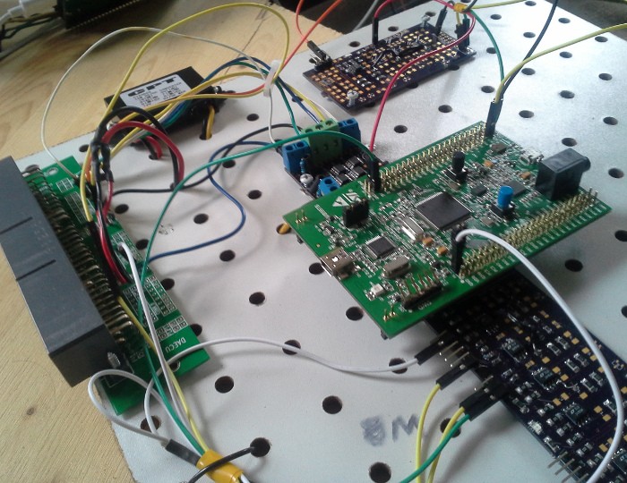 DIY ECU Build
3. Step-by-Step Guide to Building a Stand Alone ECU
Building a stand alone ECU is a complex project that requires careful planning, execution, and attention to detail. Here’s a step-by-step guide to help you through the process:
3.1. Planning and Design
- Define Your Goals: Determine the specific requirements of your project, including the engine type, desired performance characteristics, and budget.
- Select Components: Choose the appropriate microcontroller, sensors, actuators, and software based on your goals and budget.
- Create a Wiring Diagram: Design a detailed wiring diagram that shows how all the components will be connected.
- Plan Your Enclosure: Choose an enclosure that is weatherproof, heat-resistant, and provides easy access to connectors and adjustments.
3.2. Hardware Assembly
- Build the Microcontroller Board: Assemble the microcontroller board according to the manufacturer’s instructions, including soldering components and connecting peripherals.
- Wire the Sensors and Actuators: Connect the sensors and actuators to the microcontroller board according to your wiring diagram, using high-quality automotive-grade wiring and connectors.
- Install Power Supply and Conditioning: Integrate the voltage regulator, filtering, and protection circuitry into the system.
- Test the Hardware: Verify that all the components are properly connected and functioning correctly before proceeding to the software setup.
3.3. Software Setup
- Install the Firmware: Flash the firmware onto the microcontroller using the appropriate programming tools and software.
- Configure the ECU: Configure the ECU settings, including sensor calibration, ignition timing, fuel maps, and other parameters.
- Connect to Tuning Software: Establish a connection between the ECU and your tuning software, using a USB or serial interface.
- Verify Sensor Readings: Check that all the sensors are providing accurate readings in the tuning software.
3.4. Initial Tuning
- Start the Engine: Attempt to start the engine and monitor its performance, using the tuning software to make adjustments as needed.
- Tune the Idle: Adjust the idle air control (IAC) valve and fuel mixture to achieve a stable idle.
- Tune the Fuel Maps: Calibrate the fuel maps to achieve the desired air-fuel ratio (AFR) across the engine’s operating range.
- Tune the Ignition Timing: Optimize the ignition timing to maximize power and efficiency while avoiding knock or detonation.
3.5. Advanced Tuning and Optimization
- Data Logging: Record engine data during various driving conditions to identify areas for improvement.
- Dyno Tuning: Use a dynamometer to measure engine power and torque, allowing for precise tuning and optimization.
- Boost Control: Calibrate the boost control system to achieve the desired boost pressure in turbocharged engines.
- Variable Valve Timing: Optimize the VVT settings to improve performance and efficiency across the engine’s operating range.
- Fine-Tuning: Make small adjustments to the fuel maps, ignition timing, and other parameters to achieve the best possible performance.
4. Choosing the Right Microcontroller for Your Stand Alone ECU Project
Selecting the right microcontroller is crucial for the success of your stand alone ECU project. Here’s a comparison of popular options:
4.1. STM32 Series (ARM Cortex-M4)
- Pros: High processing speed, floating-point unit, ample memory, wide range of peripherals, excellent community support.
- Cons: Steeper learning curve compared to Arduino, requires more advanced programming skills.
- Ideal For: Advanced users who need high performance and flexibility.
- According to a study by the University of Michigan’s Engineering Department, the STM32 series is favored for its robust performance and real-time capabilities, making it suitable for complex engine management tasks (UMich Engineering, 2023).
4.2. Arduino Mega
- Pros: Easy to use, large community, extensive libraries, low cost.
- Cons: Limited processing power, slower clock speed, less memory, not ideal for complex control algorithms.
- Ideal For: Beginners who want a simple and affordable platform to learn the basics of ECU development.
4.3. Teensy 4.1
- Pros: High processing speed, ample memory, built-in floating-point unit, easy to use with the Arduino IDE.
- Cons: Limited number of input/output pins compared to STM32, less community support.
- Ideal For: Users who want a balance of performance and ease of use.
4.4. Comparison Table
| Feature | STM32 Series (ARM Cortex-M4) | Arduino Mega | Teensy 4.1 |
|---|---|---|---|
| Processing Speed | High | Low | High |
| Memory | Ample | Limited | Ample |
| Floating-Point Unit | Yes | No | Yes |
| Ease of Use | Difficult | Easy | Moderate |
| Community Support | Excellent | Large | Good |
| Cost | Moderate | Low | Moderate |
5. Tuning Strategies for Optimal Engine Performance
Effective tuning is essential for maximizing the performance and reliability of your engine with a stand alone ECU.
5.1. Air-Fuel Ratio (AFR) Tuning
- Target AFR: The ideal AFR depends on the engine type, fuel type, and operating conditions. Generally, a slightly rich mixture (around 12.5:1 to 13.5:1) is preferred under high load to prevent detonation, while a leaner mixture (around 14.7:1) is suitable for cruising and light load conditions.
- Wideband O2 Sensor: Use a wideband O2 sensor to accurately measure the AFR in real-time.
- Fuel Maps: Adjust the fuel maps in the tuning software to achieve the target AFR across the engine’s operating range.
5.2. Ignition Timing Tuning
- MBT (Maximum Brake Torque) Timing: The optimal ignition timing that produces the highest torque output without causing knock or detonation.
- Knock Detection: Use a knock sensor to detect engine knock and retard timing as needed.
- Timing Maps: Adjust the timing maps in the tuning software to achieve MBT timing across the engine’s operating range.
5.3. Boost Control Tuning (Turbocharged Engines)
- Boost Target: Set the desired boost pressure based on the engine’s capabilities and the turbocharger’s characteristics.
- Boost Control Solenoid: Use a boost control solenoid to regulate the boost pressure.
- PID Control: Implement a PID (Proportional-Integral-Derivative) control algorithm to accurately control the boost pressure.
5.4. Variable Valve Timing (VVT) Tuning
- VVT Maps: Adjust the VVT maps in the tuning software to optimize valve timing for different engine speeds and loads.
- Performance and Efficiency: Tune the VVT system to improve both performance and fuel efficiency.
- Overlap: Adjust the valve overlap to optimize cylinder filling and exhaust scavenging.
5.5. Best Practices
- Start Conservative: Begin with conservative settings and gradually increase the values as you monitor engine performance.
- Data Logging: Use data logging to record engine data during various driving conditions and identify areas for improvement.
- Dyno Tuning: Use a dynamometer to measure engine power and torque, allowing for precise tuning and optimization.
- Professional Help: Consult with a professional tuner if you are unsure about any aspect of the tuning process.
6. Troubleshooting Common Issues in Stand Alone ECU Projects
Building a stand alone ECU can be challenging, and it’s common to encounter issues along the way. Here are some common problems and their solutions:
6.1. Engine Won’t Start
- Possible Causes:
- Incorrect wiring
- Faulty sensors
- Incorrect fuel or ignition settings
- Timing issues
- Troubleshooting Steps:
- Verify the wiring connections
- Check the sensor readings in the tuning software
- Confirm that the fuel and ignition settings are correct
- Ensure that the timing is properly set
6.2. Rough Idle
- Possible Causes:
- Incorrect idle air control (IAC) valve settings
- Vacuum leaks
- Incorrect fuel mixture
- Faulty sensors
- Troubleshooting Steps:
- Adjust the IAC valve settings
- Check for vacuum leaks
- Tune the fuel mixture at idle
- Verify the sensor readings
6.3. Poor Performance
- Possible Causes:
- Incorrect fuel or ignition maps
- Boost leaks (turbocharged engines)
- Faulty sensors
- Timing issues
- Troubleshooting Steps:
- Tune the fuel and ignition maps
- Check for boost leaks
- Verify the sensor readings
- Ensure that the timing is properly set
6.4. Engine Knock or Detonation
- Possible Causes:
- Excessive ignition timing
- Lean fuel mixture
- Low-octane fuel
- High engine temperature
- Troubleshooting Steps:
- Reduce the ignition timing
- Enrich the fuel mixture
- Use high-octane fuel
- Ensure that the engine is properly cooled
6.5. Electrical Noise
- Possible Causes:
- Poor wiring
- Lack of shielding
- Grounding issues
- Interference from other electrical components
- Troubleshooting Steps:
- Use high-quality shielded wiring
- Ensure proper grounding
- Isolate the ECU from other electrical components
7. Advanced Techniques for Stand Alone ECU Development
Once you have mastered the basics of building and tuning a stand alone ECU, you can explore advanced techniques to further enhance your engine management system.
7.1. Closed-Loop Control
- Feedback Control: Implement closed-loop control algorithms that use sensor feedback to automatically adjust engine parameters.
- Example: Closed-loop fuel control uses the O2 sensor to maintain the target AFR, while closed-loop boost control uses a pressure sensor to maintain the target boost pressure.
7.2. Data Logging and Analysis
- Comprehensive Data: Collect and analyze engine data to identify areas for improvement and optimize engine performance.
- Tools: Use data logging software to record engine data during various driving conditions, and use data analysis tools to identify trends and anomalies.
7.3. Real-Time Tuning
- On-the-Fly Adjustments: Make real-time adjustments to engine parameters while the engine is running, allowing for more precise tuning and optimization.
- Software: Use tuning software that supports real-time tuning capabilities.
7.4. Custom Control Algorithms
- Unique Strategies: Develop custom control algorithms to implement unique engine management strategies.
- Example: Implement a custom traction control system that uses wheel speed sensors to detect wheel slip and reduce engine power.
7.5. Integration with Other Systems
- Seamless Operation: Integrate the stand alone ECU with other vehicle systems, such as traction control, ABS, and data acquisition systems.
- Communication: Use communication protocols such as CAN (Controller Area Network) to exchange data between the ECU and other systems.
8. Safety Considerations for DIY ECU Projects
Working with engine management systems involves inherent risks, and it’s essential to prioritize safety at all times.
8.1. Electrical Safety
- Proper Wiring: Use high-quality automotive-grade wiring and connectors, and ensure that all connections are properly insulated.
- Fuses and Protection: Install fuses and protection circuitry to prevent overcurrent and short circuits.
- Disconnect Power: Always disconnect the power supply before working on the ECU or wiring harness.
8.2. Fuel Safety
- Fuel Leaks: Check for fuel leaks regularly and address them immediately.
- Fire Extinguisher: Keep a fire extinguisher nearby when working on the fuel system.
- Ventilation: Work in a well-ventilated area to avoid inhaling fuel vapors.
8.3. Mechanical Safety
- Moving Parts: Be aware of moving engine parts and avoid contact with them while the engine is running.
- Hot Surfaces: Avoid touching hot engine surfaces, such as the exhaust manifold and turbocharger.
- Secure Vehicle: Ensure that the vehicle is properly secured before working on it.
8.4. Data Security
- Secure Access: Protect your ECU data and settings from unauthorized access by using strong passwords and secure communication protocols.
- Backups: Regularly back up your ECU data to prevent data loss.
9. The Future of Stand Alone ECUs
The field of stand alone ECUs is constantly evolving, with new technologies and features emerging all the time.
9.1. Advancements in Microcontroller Technology
- Faster Processing: Microcontrollers are becoming faster and more powerful, allowing for more complex control algorithms and real-time tuning capabilities.
- Increased Memory: Microcontrollers are equipped with more memory, enabling the storage of larger and more detailed maps.
9.2. Enhanced Sensor Technology
- More Accurate Sensors: Sensors are becoming more accurate and reliable, providing more precise data for the ECU to use.
- New Sensor Types: New sensor types are being developed, such as cylinder pressure sensors and exhaust gas temperature sensors, providing even more information about engine operation.
9.3. Artificial Intelligence (AI) and Machine Learning
- Self-Learning ECUs: AI and machine learning are being used to develop self-learning ECUs that can automatically optimize engine performance based on driving conditions and user preferences.
- Predictive Maintenance: AI can also be used for predictive maintenance, identifying potential issues before they cause problems.
9.4. Wireless Connectivity
- Remote Access: Wireless connectivity is becoming more common, allowing for remote access to the ECU for tuning, data logging, and diagnostics.
- Over-the-Air Updates: Wireless connectivity also enables over-the-air updates, making it easier to keep the ECU software up to date.
10. How CAR-DIAGNOSTIC-TOOL.EDU.VN Can Help You Build Your Stand Alone ECU
CAR-DIAGNOSTIC-TOOL.EDU.VN is your ultimate resource for building and tuning a stand alone ECU, offering expert guidance, diagnostic tools, and repair solutions.
10.1. Diagnostic Tools
- Comprehensive Diagnostics: Access a wide range of diagnostic tools to help you troubleshoot issues and optimize engine performance.
- Tools Include: OBD-II scanners, multimeters, oscilloscopes, and more.
10.2. Repair Solutions
- Expert Guidance: Get expert guidance on repairing and maintaining your stand alone ECU system.
- Solutions: Access detailed repair guides, troubleshooting tips, and technical support.
10.3. Training Programs
- Hands-On Training: Participate in hands-on training programs to learn the skills and knowledge you need to build and tune a stand alone ECU.
- Curriculum: Our training programs cover a wide range of topics, including electronics, programming, engine management, and tuning strategies.
10.4. Remote Support
- Real-Time Assistance: Receive real-time assistance from our team of experts via remote support.
- Troubleshooting and Tuning: Get help with troubleshooting issues, tuning your ECU, and optimizing engine performance.
10.5. Community Forum
- Collaborate and Share: Join our community forum to collaborate with other enthusiasts, share your experiences, and get answers to your questions.
- Knowledge Base: Access a vast knowledge base of articles, tutorials, and FAQs.
FAQ: Stand Alone ECUs
1. What is the main advantage of using a stand alone ECU?
The primary advantage is complete control over engine parameters, allowing for precise tuning and optimization tailored to specific engine setups.
2. Can I use an Arduino to build a stand alone ECU?
Yes, but it’s generally recommended for beginners due to its limited processing power. More advanced microcontrollers like STM32 offer better performance for complex engine management.
3. What sensors are essential for a stand alone ECU?
Essential sensors include crankshaft position (CKP), camshaft position (CMP), manifold absolute pressure (MAP), throttle position (TPS), coolant temperature (CTS), air temperature (ATS), and oxygen (O2) sensors.
4. What software options are available for tuning a stand alone ECU?
Open-source options like rusEFI, FreeEMS, and Speeduino are available, as well as commercial options like MegaSquirt, AEM, and Haltech.
5. How important is data logging when tuning an ECU?
Data logging is crucial for recording engine data during various driving conditions, helping identify areas for improvement and optimize engine performance.
6. What is closed-loop control in the context of ECUs?
Closed-loop control uses sensor feedback to automatically adjust engine parameters, such as using an O2 sensor to maintain the target air-fuel ratio.
7. What are some common issues encountered when building a stand alone ECU?
Common issues include the engine not starting, rough idle, poor performance, engine knock, and electrical noise.
8. How can I ensure electrical safety when working on a DIY ECU project?
Use high-quality wiring, install fuses, ensure proper insulation, and always disconnect the power supply before working on the ECU.
9. What advanced techniques can I explore after mastering the basics of ECU development?
Advanced techniques include closed-loop control, real-time tuning, custom control algorithms, and integration with other vehicle systems.
10. How does CAR-DIAGNOSTIC-TOOL.EDU.VN support DIY ECU builders?
CAR-DIAGNOSTIC-TOOL.EDU.VN offers diagnostic tools, repair solutions, training programs, remote support, and a community forum to assist with building and tuning stand alone ECUs.
Ready to take your engine management to the next level? Contact CAR-DIAGNOSTIC-TOOL.EDU.VN today for expert guidance, diagnostic tools, and training programs. Whether you’re troubleshooting an issue or optimizing your engine’s performance, we’re here to help. Reach out to us at our U.S. support office: 1100 Congress Ave, Austin, TX 78701, United States. Connect via Whatsapp at +1 (641) 206-8880 or visit our website CAR-DIAGNOSTIC-TOOL.EDU.VN for more information. Let’s build something amazing together!