ECU-B on a 1998 Toyota Corolla primarily powers the Supplemental Restraint System (SRS) airbag system and seat belt pretensioners. At CAR-DIAGNOSTIC-TOOL.EDU.VN, we provide comprehensive diagnostic tools, detailed repair guides, and expert technical support to ensure your vehicle’s safety systems function optimally. Our services also extend to advanced technician training and remote support, guaranteeing you have the skills and assistance needed to keep your Corolla in top condition.
Contents
- 1. Understanding the ECU-B Fuse in Your 1998 Toyota Corolla
- 1.1. What is the ECU-B Fuse?
- 1.2. Location of the ECU-B Fuse
- 1.3. Components Powered by the ECU-B Fuse
- 1.4. Why is the ECU-B Fuse Important?
- 1.5. Common Symptoms of a Blown ECU-B Fuse
- 1.6. Diagnosing a Blown ECU-B Fuse
- 1.7. Step-by-Step Guide to Replacing the ECU-B Fuse
- 1.8. Potential Causes for a Repeatedly Blown ECU-B Fuse
- 1.9. Precautions When Working with the SRS Airbag System
- 1.10. Maintaining Your 1998 Toyota Corolla’s Electrical System
- 1.11. Advanced Troubleshooting Techniques
- 1.12. Utilizing CAR-DIAGNOSTIC-TOOL.EDU.VN Resources
- 2. Decoding the Fuse Box Diagram of Your 1998 Toyota Corolla
- 2.1. What is a Fuse Box Diagram?
- 2.2. Why is the Fuse Box Diagram Important?
- 2.3. Where to Find the Fuse Box Diagram
- 2.4. Types of Fuse Boxes in a 1998 Toyota Corolla
- 2.5. Interpreting the Fuse Box Diagram
- 2.6. Common Fuses and Their Functions
- 2.7. Step-by-Step Guide to Locating a Specific Fuse
- 2.8. Common Mistakes to Avoid
- 2.9. Advanced Troubleshooting with the Fuse Box Diagram
- 2.10. Utilizing CAR-DIAGNOSTIC-TOOL.EDU.VN Resources
- 2.11. Maintaining Your Fuse Boxes
- 3. Troubleshooting Electrical Issues Related to the ECU-B Fuse
- 3.1. Common Electrical Issues Affecting the ECU-B Fuse
- 3.2. Tools and Equipment Needed for Troubleshooting
- 3.3. Step-by-Step Troubleshooting Guide
- 3.4. Advanced Troubleshooting Techniques
- 3.5. Precautions When Working with Electrical Systems
- 3.6. Utilizing CAR-DIAGNOSTIC-TOOL.EDU.VN Resources
- 4. Utilizing Diagnostic Tools for ECU-B Fuse Related Issues
- 4.1. Importance of Diagnostic Tools
- 4.2. Types of Diagnostic Tools
- 4.3. How to Use Diagnostic Tools for ECU-B Fuse Issues
- 4.4. Specific Diagnostic Tests for the ECU-B Circuit
- 4.5. Interpreting Test Results
- 4.6. Precautions When Using Diagnostic Tools
- 4.7. How CAR-DIAGNOSTIC-TOOL.EDU.VN Supports Your Diagnostic Efforts
- 4.8. Maximizing Efficiency with the Right Tools
- 5. Professional Assistance and Training Programs for Technicians
- 5.1. When to Seek Professional Assistance
- 5.2. Benefits of Professional Diagnostic Services
- 5.3. What to Expect from a Professional Diagnostic Service
1. Understanding the ECU-B Fuse in Your 1998 Toyota Corolla
The ECU-B fuse in a 1998 Toyota Corolla is a critical component in the vehicle’s electrical system, specifically designed to safeguard the Supplemental Restraint System (SRS) and seat belt pretensioners. Understanding its function and troubleshooting potential issues can significantly enhance vehicle safety and reliability.
1.1. What is the ECU-B Fuse?
The ECU-B fuse is a small protective device in the vehicle’s fuse box. Its primary role is to protect the SRS airbag system and seat belt pretensioners from electrical overloads. According to Toyota’s service manuals, the “ECU” stands for Electronic Control Unit, and “B” typically denotes a backup or battery-supplied circuit. This means that the ECU-B fuse ensures continuous power supply to the SRS components, even when the ignition is off.
1.2. Location of the ECU-B Fuse
The ECU-B fuse is typically located in the interior fuse box, often found under the dashboard on the driver’s side. To locate it precisely:
- Consult the owner’s manual for the exact location of the fuse box.
- Use a fuse puller to gently remove the fuse for inspection.
- Refer to the fuse box diagram to identify the ECU-B fuse.
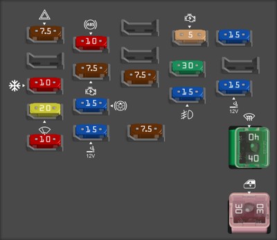
 1998 Toyota Corolla instrument panel fuse box diagramAlt text: 1998 Toyota Corolla ECU-B fuse location and diagram. Use CAR-DIAGNOSTIC-TOOL.EDU.VN for expert guidance on fuse identification.
At CAR-DIAGNOSTIC-TOOL.EDU.VN, we offer detailed diagrams and troubleshooting guides to assist you in locating and identifying various fuses in your vehicle.
1.3. Components Powered by the ECU-B Fuse
The ECU-B fuse primarily powers:
- SRS Airbag System: This includes the airbag control module, sensors, and airbags themselves.
- Seat Belt Pretensioners: These devices tighten the seat belts during a collision to secure the occupant.
1.4. Why is the ECU-B Fuse Important?
The ECU-B fuse is crucial because it ensures the continuous operation of safety systems designed to protect occupants during a collision. A blown ECU-B fuse can disable the airbags and seat belt pretensioners, significantly increasing the risk of injury in an accident.
1.5. Common Symptoms of a Blown ECU-B Fuse
- SRS Warning Light: The most common symptom is the illumination of the SRS or airbag warning light on the instrument panel.
- Non-Functional Airbags: In the event of a collision, the airbags may not deploy.
- Non-Functional Seat Belt Pretensioners: The seat belt pretensioners may not activate during a crash.
1.6. Diagnosing a Blown ECU-B Fuse
Diagnosing a blown ECU-B fuse involves a systematic approach to identify and rectify the underlying issue:
-
Visual Inspection:
- Remove the fuse and visually inspect it. A blown fuse typically has a broken filament or a dark, burnt appearance.
- Use a flashlight to get a better view of the fuse element.
-
Continuity Testing:
- Use a multimeter to test the fuse for continuity. Set the multimeter to the continuity setting (usually indicated by a diode symbol or an audible beep).
- Place the multimeter probes on each end of the fuse. If the multimeter shows continuity (beeps or displays a value close to zero ohms), the fuse is good. If there is no continuity, the fuse is blown.
-
Check the Fuse Socket:
- Ensure the fuse socket is clean and free from corrosion. Corrosion can prevent proper contact and cause the fuse to blow prematurely.
- Use a small brush or contact cleaner to clean the fuse socket if necessary.
-
Inspect Wiring:
- Check the wiring connected to the SRS airbag system and seat belt pretensioners for any signs of damage, such as frayed wires, exposed conductors, or melted insulation.
- Pay close attention to areas where the wiring may be pinched or rubbing against metal components.
-
Scan for Diagnostic Trouble Codes (DTCs):
- Use an OBD-II scanner to check for any diagnostic trouble codes (DTCs) related to the SRS airbag system.
- DTCs can provide valuable information about the specific components or circuits that are malfunctioning.
-
Professional Assistance:
- If you are not comfortable performing these diagnostic steps, or if you are unable to identify the cause of the blown fuse, seek assistance from a qualified mechanic.
- Attempting to repair the SRS airbag system without proper training and equipment can be dangerous.
1.7. Step-by-Step Guide to Replacing the ECU-B Fuse
Replacing the ECU-B fuse is a straightforward process, but it’s essential to follow these steps carefully:
- Turn Off the Ignition: Ensure the vehicle’s ignition is turned off to prevent electrical shorts.
- Locate the Fuse Box: Refer to the owner’s manual to find the fuse box location.
- Identify the ECU-B Fuse: Use the fuse box diagram to identify the ECU-B fuse.
- Remove the Blown Fuse: Use a fuse puller to gently remove the blown fuse.
- Inspect the Fuse: Visually inspect the fuse to confirm it is blown.
- Install a New Fuse: Replace the blown fuse with a new fuse of the same amperage rating. Using a fuse with a higher rating can damage the electrical system.
- Test the System: Turn on the ignition and check if the SRS warning light is off. If the light remains on, there may be an underlying issue that needs further diagnosis.
1.8. Potential Causes for a Repeatedly Blown ECU-B Fuse
If the ECU-B fuse blows repeatedly, it indicates a more significant underlying problem. Common causes include:
- Short Circuit: A short circuit in the wiring of the SRS airbag system or seat belt pretensioners can cause the fuse to blow.
- Faulty Components: A malfunctioning airbag control module, sensor, or pretensioner can draw excessive current and blow the fuse.
- Wiring Damage: Damaged or frayed wiring can create a short circuit.
- Moisture Intrusion: Moisture in the electrical connectors can cause corrosion and short circuits.
1.9. Precautions When Working with the SRS Airbag System
Working with the SRS airbag system requires extreme caution. Incorrect handling can lead to accidental airbag deployment, causing serious injury. Always follow these precautions:
- Disconnect the Battery: Before working on any part of the SRS, disconnect the negative battery cable and wait at least 10 minutes to allow the system to discharge.
- Avoid Static Electricity: Ground yourself to prevent static electricity, which can trigger airbag deployment.
- Handle Components Carefully: Handle airbag modules and sensors with care. Avoid dropping or subjecting them to impact.
- Follow Service Manual Procedures: Always follow the procedures outlined in the Toyota service manual.
- Seek Professional Help: If you are not comfortable working with the SRS, seek assistance from a qualified mechanic.
1.10. Maintaining Your 1998 Toyota Corolla’s Electrical System
Regular maintenance of your vehicle’s electrical system can prevent many issues, including blown fuses. Here are some tips:
- Regular Inspections: Periodically inspect fuses and wiring for signs of damage or corrosion.
- Professional Check-ups: Have your vehicle’s electrical system inspected by a qualified mechanic during routine maintenance.
- Proper Fuse Replacement: Always replace blown fuses with fuses of the correct amperage rating.
- Address Issues Promptly: Address any electrical issues promptly to prevent further damage.
1.11. Advanced Troubleshooting Techniques
For advanced troubleshooting of the ECU-B circuit, consider the following techniques:
- Voltage Drop Testing: Perform voltage drop tests on the wiring to identify areas of high resistance.
- Insulation Resistance Testing: Use an insulation resistance tester to check for shorts to ground in the wiring.
- Component Testing: Use a multimeter or oscilloscope to test the airbag control module, sensors, and pretensioners.
1.12. Utilizing CAR-DIAGNOSTIC-TOOL.EDU.VN Resources
CAR-DIAGNOSTIC-TOOL.EDU.VN offers a wealth of resources to help you diagnose and repair electrical issues in your 1998 Toyota Corolla:
- Detailed Wiring Diagrams: Access comprehensive wiring diagrams for the SRS airbag system and other electrical components.
- Troubleshooting Guides: Utilize our step-by-step troubleshooting guides to diagnose common electrical issues.
- Technical Support: Contact our team of experienced technicians for expert advice and support.
- Training Programs: Enroll in our training programs to enhance your diagnostic and repair skills.
By understanding the function of the ECU-B fuse and following these diagnostic and maintenance tips, you can ensure the safety and reliability of your 1998 Toyota Corolla’s SRS airbag system. Remember, CAR-DIAGNOSTIC-TOOL.EDU.VN is here to support you with the tools, resources, and expertise you need to keep your vehicle in top condition. For further assistance, contact us at +1 (641) 206-8880 or visit our office at 1100 Congress Ave, Austin, TX 78701, United States.
2. Decoding the Fuse Box Diagram of Your 1998 Toyota Corolla
Understanding the fuse box diagram of your 1998 Toyota Corolla is crucial for diagnosing and resolving electrical issues. This section provides a detailed breakdown of how to interpret the diagram, locate specific fuses, and ensure you’re using the correct replacement. CAR-DIAGNOSTIC-TOOL.EDU.VN offers comprehensive resources and expert support to help you navigate your vehicle’s electrical system with confidence.
2.1. What is a Fuse Box Diagram?
A fuse box diagram is a visual representation of the fuse layout in your vehicle. It identifies each fuse’s location and its corresponding circuit. This diagram is typically found inside the fuse box cover or in the owner’s manual.
2.2. Why is the Fuse Box Diagram Important?
The fuse box diagram is essential for:
- Identifying Blown Fuses: Quickly locate the fuse associated with a malfunctioning component.
- Replacing Fuses: Ensure you replace a blown fuse with one of the correct amperage.
- Troubleshooting Electrical Issues: Understand the circuits and components protected by each fuse.
2.3. Where to Find the Fuse Box Diagram
The fuse box diagram is commonly located:
- Inside the Fuse Box Cover: Often, a sticker or label is attached to the inside of the fuse box cover.
- Owner’s Manual: The diagram is typically included in the vehicle’s owner’s manual.
- Online Resources: CAR-DIAGNOSTIC-TOOL.EDU.VN provides access to fuse box diagrams for various makes and models, including the 1998 Toyota Corolla.
2.4. Types of Fuse Boxes in a 1998 Toyota Corolla
A 1998 Toyota Corolla typically has two fuse boxes:
- Engine Compartment Fuse Box: Located under the hood, this fuse box contains fuses for critical engine components and systems like the starter, headlights, and cooling fan.
- Interior Fuse Box: Usually found under the dashboard on the driver’s side, this fuse box houses fuses for interior components such as the radio, lights, and power windows.
2.5. Interpreting the Fuse Box Diagram
To effectively use the fuse box diagram:
- Orientation: Ensure you orient the diagram correctly to match the physical layout of the fuse box.
- Fuse Labels: Each fuse location is labeled with a number or code.
- Circuit Descriptions: The diagram includes a description of the circuit protected by each fuse.
- Amperage Ratings: Each fuse is labeled with its amperage rating (e.g., 7.5A, 10A, 15A).
2.6. Common Fuses and Their Functions
Here are some common fuses found in a 1998 Toyota Corolla and their functions:
| Fuse Label | Amperage | Function |
|---|---|---|
| HEAD | 10A | Headlights |
| TAIL | 15A | Tail Lights, License Plate Lights |
| CIG | 15A | Cigarette Lighter, Radio |
| ECU-B | 7.5A | SRS Airbag System, Seat Belt Pretensioners |
| EFI | 15A | Multiport Fuel Injection System |
| HORN | 10A | Horn |
| WIP | 20A | Windshield Wipers |
| STOP | 15A | Stop Lights |
| TURN | 7.5A | Turn Signal Lights |
| GAUGE | 10A | Gauges and Meters |
| D/L | 30A | Power Door Locks |
| POWER | 30A | Power Windows |
| DEF | 40A | Rear Window Defogger |
| ALT-S | 5A | Charging System |
2.7. Step-by-Step Guide to Locating a Specific Fuse
- Identify the Malfunctioning Component: Determine which component is not working correctly (e.g., headlights, radio).
- Consult the Owner’s Manual or Fuse Box Diagram: Find the fuse box diagram for your vehicle.
- Locate the Fuse: Use the diagram to find the fuse associated with the malfunctioning component.
- Remove the Fuse: Use a fuse puller to gently remove the fuse.
- Inspect the Fuse: Check the fuse for a broken filament. If the fuse is blown, replace it with a new fuse of the same amperage rating.
2.8. Common Mistakes to Avoid
- Using the Wrong Amperage Fuse: Always use a fuse with the correct amperage rating. Using a fuse with a higher rating can damage the electrical system and pose a fire risk.
- Ignoring the Fuse Box Diagram: Never guess which fuse to replace. Always consult the fuse box diagram.
- Overlooking Underlying Issues: If a fuse blows repeatedly, it indicates an underlying issue that needs to be addressed.
- Forcing Fuses: Never force a fuse into the socket. If it doesn’t fit easily, double-check that you have the correct fuse and orientation.
2.9. Advanced Troubleshooting with the Fuse Box Diagram
The fuse box diagram can also be used for advanced troubleshooting:
- Identifying Circuit Overloads: If multiple components on the same circuit are malfunctioning, it may indicate an overload.
- Tracing Wiring Issues: The diagram can help you trace the wiring path of a circuit to identify potential shorts or open circuits.
- Understanding System Interdependencies: The diagram can reveal how different systems are interconnected, helping you diagnose complex electrical issues.
2.10. Utilizing CAR-DIAGNOSTIC-TOOL.EDU.VN Resources
CAR-DIAGNOSTIC-TOOL.EDU.VN provides a range of resources to help you effectively use your vehicle’s fuse box diagram:
- Detailed Fuse Box Diagrams: Access high-quality, detailed fuse box diagrams for the 1998 Toyota Corolla.
- Troubleshooting Guides: Utilize our step-by-step troubleshooting guides to diagnose and resolve electrical issues.
- Technical Support: Contact our team of experienced technicians for expert advice and support.
- Training Programs: Enroll in our training programs to enhance your diagnostic and repair skills.
2.11. Maintaining Your Fuse Boxes
Regular maintenance of your fuse boxes can prevent many electrical issues:
- Keep Fuse Boxes Clean: Keep the fuse boxes free from dirt, moisture, and corrosion.
- Inspect Fuses Regularly: Periodically inspect fuses for signs of damage or corrosion.
- Proper Fuse Replacement: Always replace blown fuses with fuses of the correct amperage rating.
- Secure Fuse Box Covers: Ensure the fuse box covers are securely in place to protect the fuses from the elements.
By understanding and effectively using the fuse box diagram, you can diagnose and resolve electrical issues in your 1998 Toyota Corolla with confidence. Remember, CAR-DIAGNOSTIC-TOOL.EDU.VN is here to provide the tools, resources, and expertise you need to keep your vehicle in top condition. For further assistance, contact us at +1 (641) 206-8880 or visit our office at 1100 Congress Ave, Austin, TX 78701, United States.
3. Troubleshooting Electrical Issues Related to the ECU-B Fuse
Electrical problems can be frustrating, but with the right knowledge and tools, you can effectively diagnose and resolve issues related to the ECU-B fuse in your 1998 Toyota Corolla. CAR-DIAGNOSTIC-TOOL.EDU.VN offers a comprehensive suite of resources, including advanced diagnostic tools, detailed troubleshooting guides, and expert technical support, to help you tackle these challenges.
3.1. Common Electrical Issues Affecting the ECU-B Fuse
Several electrical issues can cause the ECU-B fuse to blow repeatedly or lead to malfunctions in the SRS airbag system and seat belt pretensioners. Understanding these common problems is the first step in effective troubleshooting.
-
Short Circuits:
- A short circuit occurs when there is an unintended electrical connection between two points in a circuit. This can cause excessive current flow, leading to a blown fuse.
- Common causes of short circuits include damaged wiring, frayed insulation, and corrosion.
-
Overloads:
- An overload happens when a circuit draws more current than it is designed to handle. This can be due to a faulty component or excessive load on the circuit.
- Overloads can cause the ECU-B fuse to blow repeatedly.
-
Faulty Components:
- A malfunctioning airbag control module, sensor, or seat belt pretensioner can draw excessive current, causing the ECU-B fuse to blow.
- Faulty components can also lead to malfunctions in the SRS airbag system and seat belt pretensioners.
-
Wiring Problems:
- Damaged, corroded, or loose wiring can cause a variety of electrical issues, including blown fuses, intermittent malfunctions, and complete system failures.
- Wiring problems are often caused by age, environmental factors, and physical damage.
-
Grounding Issues:
- A poor or missing ground connection can cause electrical noise, voltage fluctuations, and malfunctions in the SRS airbag system and seat belt pretensioners.
- Grounding issues can also lead to blown fuses and intermittent problems.
3.2. Tools and Equipment Needed for Troubleshooting
To effectively troubleshoot electrical issues related to the ECU-B fuse, you will need the following tools and equipment:
-
Multimeter:
- A multimeter is an essential tool for measuring voltage, current, and resistance in electrical circuits.
- Use a multimeter to test for continuity, voltage drops, and shorts to ground.
-
OBD-II Scanner:
- An OBD-II scanner allows you to read diagnostic trouble codes (DTCs) from the vehicle’s computer.
- DTCs can provide valuable information about the specific components or circuits that are malfunctioning.
-
Fuse Puller:
- A fuse puller is a small plastic tool used to safely remove fuses from the fuse box.
- Using a fuse puller prevents damage to the fuse and the fuse box.
-
Wiring Diagram:
- A wiring diagram provides a detailed map of the vehicle’s electrical circuits.
- Use a wiring diagram to trace circuits and identify potential problem areas.
-
Test Light:
- A test light is a simple tool used to check for the presence of voltage in a circuit.
- Use a test light to quickly verify that a circuit is receiving power.
-
Wire Strippers and Crimpers:
- Wire strippers and crimpers are used to repair and modify wiring.
- Use these tools to strip insulation from wires and crimp connectors.
-
Contact Cleaner:
- Contact cleaner is used to clean electrical connectors and remove corrosion.
- Cleaning connectors can improve electrical conductivity and prevent malfunctions.
CAR-DIAGNOSTIC-TOOL.EDU.VN offers a wide range of high-quality diagnostic tools and equipment to help you troubleshoot electrical issues in your 1998 Toyota Corolla.
3.3. Step-by-Step Troubleshooting Guide
Follow these steps to troubleshoot electrical issues related to the ECU-B fuse:
-
Check the ECU-B Fuse:
- Locate the ECU-B fuse in the fuse box.
- Remove the fuse and inspect it for damage. If the fuse is blown, replace it with a new fuse of the same amperage rating.
-
Scan for Diagnostic Trouble Codes (DTCs):
- Use an OBD-II scanner to check for any DTCs related to the SRS airbag system.
- Record the DTCs and research their meaning.
-
Inspect Wiring and Connectors:
- Visually inspect the wiring and connectors associated with the SRS airbag system and seat belt pretensioners.
- Look for signs of damage, corrosion, or loose connections.
- Pay close attention to areas where the wiring may be pinched or rubbing against metal components.
-
Test for Short Circuits:
- Use a multimeter to test for short circuits in the wiring.
- Disconnect the battery and set the multimeter to the continuity setting.
- Check for continuity between the wiring and ground.
-
Perform Voltage Drop Testing:
- Perform voltage drop tests to identify areas of high resistance in the circuit.
- Connect the multimeter to the circuit and measure the voltage drop while the circuit is in operation.
- Excessive voltage drop indicates a problem with the wiring or connectors.
-
Test Components:
- Use a multimeter or oscilloscope to test the airbag control module, sensors, and seat belt pretensioners.
- Compare the test results to the specifications in the Toyota service manual.
-
Check Ground Connections:
- Inspect the ground connections for the SRS airbag system.
- Ensure that the ground connections are clean and tight.
- Use a multimeter to check for continuity between the ground connections and the vehicle’s chassis.
-
Repair or Replace Faulty Components:
- Repair or replace any faulty wiring, connectors, or components.
- Ensure that all repairs are performed according to Toyota’s recommended procedures.
-
Clear DTCs and Retest the System:
- Clear the DTCs from the vehicle’s computer using the OBD-II scanner.
- Retest the SRS airbag system to ensure that it is functioning properly.
3.4. Advanced Troubleshooting Techniques
For complex electrical issues, consider these advanced troubleshooting techniques:
-
Insulation Resistance Testing:
- Use an insulation resistance tester to check for shorts to ground in the wiring.
- This test can help you identify hidden shorts that are difficult to find with a multimeter.
-
Oscilloscope Diagnostics:
- Use an oscilloscope to analyze the waveforms of electrical signals in the SRS airbag system.
- This can help you identify intermittent problems and subtle malfunctions.
-
Consult Toyota Service Bulletins:
- Check for any Toyota service bulletins (TSBs) related to the SRS airbag system in your 1998 Toyota Corolla.
- TSBs often contain valuable information about common problems and recommended solutions.
3.5. Precautions When Working with Electrical Systems
-
Disconnect the Battery:
- Always disconnect the negative battery cable before working on the electrical system.
- This prevents accidental shorts and electrical shock.
-
Use Proper Tools:
- Use the correct tools for the job.
- Using the wrong tools can damage the electrical system and cause injury.
-
Follow Safety Procedures:
- Follow all safety procedures outlined in the Toyota service manual.
- This includes wearing safety glasses and gloves.
-
Seek Professional Help:
- If you are not comfortable working on the electrical system, seek assistance from a qualified mechanic.
- Attempting to repair the electrical system without proper training and experience can be dangerous.
3.6. Utilizing CAR-DIAGNOSTIC-TOOL.EDU.VN Resources
CAR-DIAGNOSTIC-TOOL.EDU.VN provides a wealth of resources to help you troubleshoot electrical issues in your 1998 Toyota Corolla:
-
Detailed Wiring Diagrams:
- Access comprehensive wiring diagrams for the SRS airbag system and other electrical components.
-
Troubleshooting Guides:
- Utilize our step-by-step troubleshooting guides to diagnose common electrical issues.
-
Technical Support:
- Contact our team of experienced technicians for expert advice and support.
-
Training Programs:
- Enroll in our training programs to enhance your diagnostic and repair skills.
By following these troubleshooting steps and utilizing the resources available at CAR-DIAGNOSTIC-TOOL.EDU.VN, you can effectively diagnose and resolve electrical issues related to the ECU-B fuse in your 1998 Toyota Corolla. Remember, CAR-DIAGNOSTIC-TOOL.EDU.VN is here to support you with the tools, resources, and expertise you need to keep your vehicle in top condition. For further assistance, contact us at +1 (641) 206-8880 or visit our office at 1100 Congress Ave, Austin, TX 78701, United States.
4. Utilizing Diagnostic Tools for ECU-B Fuse Related Issues
Modern diagnostic tools can significantly simplify the process of identifying and resolving issues related to the ECU-B fuse in your 1998 Toyota Corolla. CAR-DIAGNOSTIC-TOOL.EDU.VN offers a range of advanced diagnostic tools and expert guidance to help you accurately diagnose and efficiently repair your vehicle.
4.1. Importance of Diagnostic Tools
Diagnostic tools play a crucial role in modern automotive repair:
- Accurate Diagnosis: They provide precise data to identify the root cause of the problem.
- Time Savings: They reduce the time spent on manual inspections and guesswork.
- Comprehensive Analysis: They offer a complete overview of the vehicle’s systems.
- Efficiency: They streamline the repair process, saving both time and money.
4.2. Types of Diagnostic Tools
Several diagnostic tools can be used to address ECU-B fuse related issues:
-
OBD-II Scanners:
- Function: Read and clear Diagnostic Trouble Codes (DTCs).
- Benefit: Quickly identify error codes related to the SRS system and other components.
-
Multimeters:
- Function: Measure voltage, current, and resistance.
- Benefit: Test the continuity of circuits, check for voltage drops, and identify short circuits.
-
Oscilloscopes:
- Function: Analyze electrical waveforms.
- Benefit: Detect intermittent faults and diagnose sensor issues with precision.
-
Advanced Diagnostic Scanners:
- Function: Perform advanced functions such as component testing, module programming, and live data analysis.
- Benefit: Provide in-depth analysis of the SRS system and other electronic components.
CAR-DIAGNOSTIC-TOOL.EDU.VN offers a variety of diagnostic tools to suit different needs and skill levels.
4.3. How to Use Diagnostic Tools for ECU-B Fuse Issues
Follow these steps to effectively use diagnostic tools for ECU-B fuse related problems:
-
Preliminary Inspection:
- Check the ECU-B fuse for any visible signs of damage.
- Replace the fuse if it is blown.
-
Connect the OBD-II Scanner:
- Plug the OBD-II scanner into the vehicle’s diagnostic port.
- Turn on the ignition and follow the scanner’s instructions to read DTCs.
-
Interpret Diagnostic Trouble Codes (DTCs):
- Research the meaning of the DTCs to identify the affected components or circuits.
- Common DTCs related to the SRS system include codes for airbag malfunctions, sensor issues, and wiring problems.
-
Perform Component Testing with a Multimeter:
- Use a multimeter to test the continuity and voltage of the circuits related to the ECU-B fuse.
- Check the wiring, connectors, and components for any signs of damage or corrosion.
-
Analyze Waveforms with an Oscilloscope:
- If necessary, use an oscilloscope to analyze the waveforms of the sensors and actuators in the SRS system.
- This can help you identify intermittent faults and diagnose sensor issues with precision.
-
Perform Advanced Diagnostics with a Scanner:
- Use an advanced diagnostic scanner to perform component testing, module programming, and live data analysis.
- This can provide in-depth analysis of the SRS system and other electronic components.
-
Repair or Replace Faulty Components:
- Based on the diagnostic results, repair or replace any faulty wiring, connectors, or components.
- Ensure that all repairs are performed according to Toyota’s recommended procedures.
-
Clear DTCs and Retest the System:
- Clear the DTCs from the vehicle’s computer using the OBD-II scanner.
- Retest the SRS system to ensure that it is functioning properly.
4.4. Specific Diagnostic Tests for the ECU-B Circuit
-
Continuity Test:
- Purpose: Verify the integrity of the wiring and connectors in the ECU-B circuit.
- Procedure: Disconnect the battery and use a multimeter to check for continuity between the various points in the circuit.
-
Voltage Drop Test:
- Purpose: Identify areas of high resistance in the ECU-B circuit.
- Procedure: Connect the multimeter to the circuit and measure the voltage drop while the circuit is in operation.
- Excessive voltage drop indicates a problem with the wiring or connectors.
-
Component Test:
- Purpose: Test the functionality of the airbag control module, sensors, and seat belt pretensioners.
- Procedure: Use a multimeter or oscilloscope to measure the voltage, current, and resistance of the components.
- Compare the test results to the specifications in the Toyota service manual.
4.5. Interpreting Test Results
-
Continuity Test:
- A reading of zero ohms or a beep indicates continuity.
- A reading of infinite ohms indicates a break in the circuit.
-
Voltage Drop Test:
- A voltage drop of less than 0.5 volts is typically acceptable.
- A voltage drop of more than 0.5 volts indicates excessive resistance.
-
Component Test:
- Compare the test results to the specifications in the Toyota service manual.
- Any deviations from the specifications indicate a problem with the component.
4.6. Precautions When Using Diagnostic Tools
-
Read the Manuals:
- Read the instruction manuals for all diagnostic tools before using them.
- This will help you understand how to use the tools safely and effectively.
-
Disconnect the Battery:
- Disconnect the negative battery cable before working on the electrical system.
- This prevents accidental shorts and electrical shock.
-
Use Proper Grounding:
- Ensure that all diagnostic tools are properly grounded.
- This prevents electrical noise and ensures accurate readings.
-
Follow Safety Procedures:
- Follow all safety procedures outlined in the Toyota service manual.
- This includes wearing safety glasses and gloves.
-
Seek Professional Help:
- If you are not comfortable using diagnostic tools, seek assistance from a qualified mechanic.
- Attempting to diagnose electrical problems without proper training and experience can be dangerous.
4.7. How CAR-DIAGNOSTIC-TOOL.EDU.VN Supports Your Diagnostic Efforts
CAR-DIAGNOSTIC-TOOL.EDU.VN provides a comprehensive suite of resources to support your diagnostic efforts:
-
Wide Range of Diagnostic Tools:
- We offer a variety of diagnostic tools to suit different needs and skill levels.
-
Detailed Guides and Tutorials:
- Our website features detailed guides and tutorials on how to use diagnostic tools effectively.
-
Expert Technical Support:
- Our team of experienced technicians is available to provide expert advice and support.
-
Training Programs:
- We offer training programs to enhance your diagnostic and repair skills.
4.8. Maximizing Efficiency with the Right Tools
Using the right diagnostic tools can significantly improve the efficiency of your repair efforts. By accurately diagnosing the problem and identifying the faulty components, you can reduce the time spent on trial-and-error repairs and ensure that the job is done right the first time.
CAR-DIAGNOSTIC-TOOL.EDU.VN is committed to providing you with the tools, resources, and expertise you need to diagnose and repair your 1998 Toyota Corolla effectively. For further assistance, contact us at +1 (641) 206-8880 or visit our office at 1100 Congress Ave, Austin, TX 78701, United States.
5. Professional Assistance and Training Programs for Technicians
For complex issues related to the ECU-B fuse and the SRS airbag system in your 1998 Toyota Corolla, seeking professional assistance and enrolling in specialized training programs can be highly beneficial. CAR-DIAGNOSTIC-TOOL.EDU.VN offers comprehensive support and training to enhance your diagnostic and repair skills.
5.1. When to Seek Professional Assistance
While many electrical issues can be resolved with basic troubleshooting, certain situations warrant professional intervention:
- Repeated Fuse Blows: If the ECU-B fuse continues to blow despite your efforts, it indicates a deeper underlying problem.
- Complex Diagnostic Codes: Advanced DTCs that require specialized knowledge and equipment to interpret.
- SRS Airbag System Malfunctions: Due to the safety-critical nature of the SRS, professional diagnosis and repair are recommended.
- Lack of Experience: If you are uncomfortable or unfamiliar with electrical diagnostics, seeking professional help is the safest option.
5.2. Benefits of Professional Diagnostic Services
- Expertise and Experience: Certified technicians have the knowledge and experience to accurately diagnose complex electrical issues.
- Advanced Diagnostic Equipment: Professional shops have access to high-end diagnostic tools that may not be available to the average DIYer.
- Safety: Working with the SRS airbag system can be dangerous. Professionals are trained to handle these systems safely.
- Quality Repairs: Professional repairs are typically performed to a higher standard, ensuring long-term reliability.
5.3. What to Expect from a Professional Diagnostic Service
When you take your 1998 Toyota Corolla to a professional repair shop, you can expect the following:
- Initial Assessment: The technician will gather information about the problem and perform a visual inspection of the vehicle.
- Diagnostic Testing: The technician will use diagnostic tools to read