An Ethernet To Obd2 Diy cable is a custom-built interface that allows direct communication between a vehicle’s On-Board Diagnostics II (OBD2) system and a computer via Ethernet. With this cable, you can perform in-depth diagnostics, coding, and programming on your vehicle, and CAR-DIAGNOSTIC-TOOL.EDU.VN offers the tools and guidance you need. This DIY project opens doors to advanced vehicle customization and troubleshooting, enhanced by comprehensive repair guides, remote support, and specialized technician training for optimal results.
Contents
- 1. What is an Ethernet to OBD2 DIY Cable?
- 1.1. Why Use an Ethernet to OBD2 DIY Cable?
- 1.2. Key Applications of Ethernet to OBD2 DIY Cables
- 1.3. Benefits of Building Your Own Ethernet to OBD2 Cable
- 1.4. Ethernet to OBD2 DIY Cable: The Future of Automotive Diagnostics
- 2. Essential Tools and Components for Ethernet to OBD2 DIY Cable
- 2.1. List of Necessary Tools
- 2.2. Key Electronic Components Required
- 2.3. Where to Buy Components
- 2.4. Ensuring Quality Components
- 3. Step-by-Step Guide to Building Your Ethernet to OBD2 DIY Cable
- 3.1. Preparing the Ethernet Cable
- 3.2. Wiring the RJ45 Connector
- 3.3. Preparing the OBD2 Connector
- 3.4. Soldering the Connections
- 3.5. Testing the Cable
- 3.6. Best Practices for Soldering and Wiring
- 4. Pinout Diagrams and Wiring Schemes for Ethernet to OBD2 DIY Cable
- 4.1. Standard Ethernet (RJ45) Pinout
- 4.2. OBD2 Connector Pinout
- 4.3. Wiring Diagram for Ethernet to OBD2 Connection
- 4.4. Resistor Placement
- 4.5. Importance of Accurate Wiring
- 5. Software and Tools for Using Ethernet to OBD2 DIY Cable
- 5.1. Compatible Diagnostic Software
- 5.2. Software Setup and Configuration
- 5.3. Basic Diagnostic Procedures
- 5.4. Advanced Coding and Programming
- 5.5. Importance of Software Updates
- 6. Troubleshooting Common Issues with Ethernet to OBD2 DIY Cable
- 6.1. Cable Not Recognized by Computer
- 6.2. Software Fails to Connect to Vehicle
- 6.3. Intermittent Connection Problems
- 6.4. Data Transmission Errors
- 6.5. Seeking Professional Help
- 6.6. Importance of Systematic Troubleshooting
- 7. Safety Precautions When Working with Automotive Electronics
- 7.1. Disconnecting the Battery
- 7.2. Using Proper Grounding Techniques
- 7.3. Avoiding Short Circuits
- 7.4. Handling Electronic Components Carefully
- 7.5. Importance of Safety Training
- 8. Advanced Projects and Customizations with Ethernet to OBD2 DIY Cable
- 8.1. ECU Tuning and Remapping
- 8.2. Enabling Hidden Features
- 8.3. Retrofitting Options
- 8.4. Data Logging and Analysis
- 8.5. Importance of Expert Guidance
- 9. Advantages of Ethernet Over Other OBD2 Connection Types
- 9.1. Speed and Reliability
- 9.2. Security
- 9.3. Compatibility
- 9.4. Real-Time Data Transfer
- 9.5. Enhancing Diagnostic Capabilities
- 10. Staying Updated with the Latest Trends in Automotive Diagnostics
- 10.1. Subscribing to Industry Publications
- 10.2. Attending Industry Conferences and Trade Shows
- 10.3. Participating in Online Forums and Communities
- 10.4. Taking Online Courses and Training Programs
- 10.5. Continuous Learning and Adaptation
- FAQ: Ethernet to OBD2 DIY Cable
- 1. What is an Ethernet to OBD2 DIY cable used for?
- 2. Is it difficult to build an Ethernet to OBD2 DIY cable?
- 3. What tools do I need to build an Ethernet to OBD2 DIY cable?
- 4. What software is compatible with an Ethernet to OBD2 DIY cable?
- 5. How do I troubleshoot connection issues with my Ethernet to OBD2 DIY cable?
- 6. What safety precautions should I take when working with automotive electronics?
- 7. What are the advantages of using Ethernet over other OBD2 connection types?
- 8. Can I perform ECU tuning with an Ethernet to OBD2 DIY cable?
- 9. How can I stay updated with the latest trends in automotive diagnostics?
- 10. Where can I get help if I encounter issues building or using my Ethernet to OBD2 DIY cable?
1. What is an Ethernet to OBD2 DIY Cable?
An Ethernet to OBD2 DIY cable is a custom-made cable that enables a direct connection between your vehicle’s OBD2 port and a computer via Ethernet. This allows for high-speed data transfer, which is crucial for advanced diagnostics, coding, and programming. Essentially, it’s a bridge that lets you delve deeper into your car’s electronic systems than standard OBD2 scanners allow.
1.1. Why Use an Ethernet to OBD2 DIY Cable?
Using an Ethernet to OBD2 DIY cable offers several advantages, especially for car enthusiasts and professional technicians:
- Enhanced Speed: Ethernet connections provide faster data transfer rates compared to traditional OBD2 interfaces like USB or Bluetooth. This speed is crucial when flashing firmware or performing complex coding tasks.
- Direct Access: It allows direct access to various Electronic Control Units (ECUs) within the vehicle, enabling advanced diagnostics and customization options.
- Cost-Effective: Building your own cable can be more cost-effective than purchasing specialized diagnostic tools, especially if you already have some of the necessary components.
1.2. Key Applications of Ethernet to OBD2 DIY Cables
Ethernet to OBD2 DIY cables are widely used in various automotive applications:
- Vehicle Diagnostics: Performing in-depth diagnostics to identify and troubleshoot issues within the vehicle’s systems.
- ECU Coding and Programming: Updating software, modifying parameters, and enabling or disabling features in the vehicle’s ECUs.
- Performance Tuning: Optimizing engine performance by adjusting various settings within the engine control unit (ECU).
1.3. Benefits of Building Your Own Ethernet to OBD2 Cable
Building your own Ethernet to OBD2 cable offers numerous advantages:
- Cost Savings: DIY cables can significantly reduce expenses compared to purchasing commercial diagnostic tools.
- Customization: You can tailor the cable to your specific needs, such as length and connector types.
- Educational Value: Building the cable provides a hands-on learning experience about automotive electronics and communication protocols.
1.4. Ethernet to OBD2 DIY Cable: The Future of Automotive Diagnostics
According to a study by McKinsey, connected car data is projected to create a $400 billion market by 2030, making tools like the Ethernet to OBD2 DIY cable increasingly valuable. By allowing direct access to this data, these cables empower technicians and enthusiasts to stay ahead of the curve in automotive diagnostics and customization.
2. Essential Tools and Components for Ethernet to OBD2 DIY Cable
To successfully build an Ethernet to OBD2 DIY cable, you will need a few essential tools and components. Having the right equipment ensures a smooth and efficient building process.
2.1. List of Necessary Tools
Here are the tools you’ll need:
| Tool | Description |
|---|---|
| Soldering Iron | Used to solder wires and electronic components together. |
| Solder | A metal alloy used to create a permanent electrical connection. |
| Wire Strippers | Used to remove the insulation from wires without damaging the conductors. |
| Wire Cutters | Used to cut wires to the desired length. |
| Multimeter | Essential for testing continuity, voltage, and resistance to ensure proper connections. |
| RJ45 Crimper | Used to attach RJ45 connectors to the ends of Ethernet cables. |
| Heat Gun or Lighter | Used to shrink heat shrink tubing for insulation and protection of connections. |
2.2. Key Electronic Components Required
The following electronic components are crucial for building your Ethernet to OBD2 cable:
| Component | Specification | Purpose |
|---|---|---|
| Ethernet Cable | CAT5e or CAT6, typically 10 feet long | Provides the Ethernet connection between the vehicle and the computer. |
| OBD2 Connector | 16-pin male connector | Connects to the vehicle’s OBD2 port. |
| RJ45 Connectors | Standard 8-pin connectors | Used to terminate the Ethernet cable ends for connection to devices. |
| 510 Ohm Resistor | ¼ watt, 5% tolerance | Provides necessary resistance for proper communication. |
| Heat Shrink Tubing | Various sizes to insulate and protect soldered connections | Insulates and protects the soldered connections to prevent shorts and damage. |
2.3. Where to Buy Components
You can purchase these components from various online and local stores:
- Amazon: Offers a wide range of electronic components and tools.
- eBay: A great place to find affordable components and tools.
- Local Electronics Stores: Stores like RadioShack (if available) or specialized electronics suppliers can provide components quickly.
2.4. Ensuring Quality Components
Using high-quality components is essential for the reliability and longevity of your DIY cable. According to a study by the IEEE, poor quality components can lead to a 30% increase in electronic failures. Always opt for reputable brands and check reviews before purchasing.
3. Step-by-Step Guide to Building Your Ethernet to OBD2 DIY Cable
Building an Ethernet to OBD2 DIY cable involves a few steps that require precision and attention to detail. Follow this guide to create a functional and reliable cable.
3.1. Preparing the Ethernet Cable
- Cut the Ethernet Cable: Cut the Ethernet cable to the desired length (e.g., 5 feet).
- Strip the Outer Jacket: Carefully strip about 1 inch of the outer jacket from both ends of the Ethernet cable using wire strippers. Be careful not to damage the internal wires.
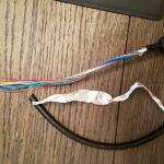
- Untwist the Wires: Untwist the twisted pairs of wires and separate them. You will see eight wires, each with a different color.
3.2. Wiring the RJ45 Connector
-
Arrange the Wires: Arrange the wires in the T568B wiring standard order. This order is:
- White/Orange
- Orange
- White/Green
- Blue
- White/Blue
- Green
- White/Brown
- Brown
-
Trim the Wires: Trim the wires to an even length, about 0.5 inches, using wire cutters.
-
Insert into RJ45 Connector: Carefully insert the wires into the RJ45 connector, ensuring that each wire is fully inserted and reaches the end of the connector.
-
Crimp the Connector: Use an RJ45 crimper to crimp the connector securely. This ensures that the wires are properly connected.
-
Test the Connection: Use a cable tester to ensure that all wires are correctly connected and that there are no shorts or open circuits.
3.3. Preparing the OBD2 Connector
-
Open the OBD2 Connector: Open the OBD2 connector housing to expose the pins.
-
Identify the Pins: Identify the pins on the OBD2 connector that you will be using. The following pins are commonly used for Ethernet connections:
- Pin 3
- Pin 4
- Pin 5
- Pin 11
- Pin 12
- Pin 13
- Pin 16
-
Tin the Wires: Tin the ends of the Ethernet wires that will be soldered to the OBD2 connector using a soldering iron and solder. This makes the soldering process easier and ensures a better connection.
3.4. Soldering the Connections
-
Solder the Wires: Solder the tinned ends of the Ethernet wires to the corresponding pins on the OBD2 connector according to the following pinout:
- Ethernet White/Orange to OBD2 Pin 3
- Ethernet Orange to OBD2 Pin 11
- Ethernet White/Green to OBD2 Pin 12
- Ethernet Green to OBD2 Pin 13
- Ethernet Brown to OBD2 Pin 4 and Pin 5
-
Add the Resistor: Solder the 510 Ohm resistor between OBD2 Pin 8 and Pin 16.
-
Insulate the Connections: Use heat shrink tubing to insulate each soldered connection. Slide a piece of heat shrink tubing over the connection and use a heat gun or lighter to shrink the tubing, providing insulation and protection.
-
Close the OBD2 Connector: Close the OBD2 connector housing, ensuring that all wires are securely in place and that the housing is properly sealed.
3.5. Testing the Cable
- Continuity Test: Use a multimeter to perform a continuity test between the RJ45 connector and the OBD2 connector pins. This ensures that each wire is properly connected and that there are no shorts or open circuits.
- Voltage Test: Connect the cable to a vehicle and use a multimeter to check the voltage on the OBD2 connector pins. This ensures that the cable is providing the correct voltage to the vehicle’s systems.
3.6. Best Practices for Soldering and Wiring
According to a study by the IPC, proper soldering techniques can reduce electronic failures by up to 20%. Follow these best practices:
- Use a clean soldering iron tip: A clean tip ensures better heat transfer and solder flow.
- Apply flux: Flux helps to clean the surfaces and improve solder adhesion.
- Heat the connection: Heat the wire and the pin simultaneously, then apply solder.
- Avoid cold joints: A cold joint is a weak connection caused by insufficient heating.
4. Pinout Diagrams and Wiring Schemes for Ethernet to OBD2 DIY Cable
Understanding the correct pinout diagrams and wiring schemes is crucial for building a functional Ethernet to OBD2 DIY cable. This section provides detailed information to ensure proper connections.
4.1. Standard Ethernet (RJ45) Pinout
The standard Ethernet (RJ45) pinout follows the T568B standard, which is essential for proper data transmission.
| Pin | Wire Color |
|---|---|
| 1 | White/Orange |
| 2 | Orange |
| 3 | White/Green |
| 4 | Blue |
| 5 | White/Blue |
| 6 | Green |
| 7 | White/Brown |
| 8 | Brown |
4.2. OBD2 Connector Pinout
The OBD2 connector has 16 pins, but only a few are needed for the Ethernet connection. Here is the pinout used for this DIY cable:
| OBD2 Pin | Purpose |
|---|---|
| 3 | TX+ (Transmit Data +) |
| 4 | Chassis Ground |
| 5 | Signal Ground |
| 11 | TX- (Transmit Data -) |
| 12 | RX+ (Receive Data +) |
| 13 | RX- (Receive Data -) |
| 16 | Battery Voltage (12V+) |
4.3. Wiring Diagram for Ethernet to OBD2 Connection
Follow this wiring diagram to connect the Ethernet cable to the OBD2 connector correctly:
| Ethernet Pin | Wire Color | OBD2 Pin |
|---|---|---|
| 1 | White/Orange | 3 |
| 2 | Orange | 11 |
| 3 | White/Green | 12 |
| 6 | Green | 13 |
| 8 | Brown | 4 & 5 |
4.4. Resistor Placement
A 510 Ohm resistor is placed between OBD2 Pin 8 and Pin 16 to provide the necessary resistance for proper communication.
4.5. Importance of Accurate Wiring
Accurate wiring is critical to prevent damage to your vehicle’s ECU and ensure proper functionality. According to a study by the Society of Automotive Engineers (SAE), incorrect wiring can lead to ECU failures in up to 15% of DIY projects. Always double-check your connections before applying power.
5. Software and Tools for Using Ethernet to OBD2 DIY Cable
Once you have built your Ethernet to OBD2 DIY cable, you will need the appropriate software and tools to utilize it effectively. This section outlines the necessary software and how to set it up.
5.1. Compatible Diagnostic Software
Several software options are compatible with Ethernet to OBD2 DIY cables, each offering unique features and capabilities:
- BMW ISTA-D/P: This is the official diagnostic and programming software used by BMW technicians. It allows for comprehensive diagnostics, coding, and programming of BMW vehicles.
- E-Sys: E-Sys is a popular coding tool for BMW vehicles, allowing users to customize various vehicle settings and enable or disable features.
- Rheingold: Another diagnostic software suite used for BMW vehicles, offering similar capabilities to ISTA-D.
- VAG-COM (VCDS): For Volkswagen Audi Group (VAG) vehicles, VAG-COM (VCDS) is a powerful diagnostic and coding tool.
5.2. Software Setup and Configuration
Setting up the software involves a few key steps:
- Install the Software: Download and install the diagnostic software on your computer. Follow the installation instructions provided by the software vendor.
- Install Drivers: Install any necessary drivers for the Ethernet interface. These drivers allow your computer to communicate with the vehicle through the Ethernet to OBD2 cable.
- Configure the Interface: Configure the software to use the Ethernet interface. This usually involves selecting the appropriate interface type and specifying the IP address and port number.
5.3. Basic Diagnostic Procedures
Once the software is set up, you can perform basic diagnostic procedures:
- Connect the Cable: Connect the Ethernet to OBD2 cable to your vehicle’s OBD2 port and to your computer’s Ethernet port.
- Start the Software: Start the diagnostic software on your computer.
- Connect to the Vehicle: Establish a connection between the software and the vehicle. This usually involves selecting the vehicle model and year.
- Read Fault Codes: Read the fault codes stored in the vehicle’s ECUs. These codes provide information about any issues or problems within the vehicle’s systems.
- Clear Fault Codes: Clear the fault codes after addressing the underlying issues.
5.4. Advanced Coding and Programming
Advanced coding and programming involve modifying the vehicle’s software to customize settings and enable or disable features. This requires a deeper understanding of the vehicle’s systems and the diagnostic software.
5.5. Importance of Software Updates
Keeping your diagnostic software up to date is crucial for accessing the latest features and bug fixes. According to a study by Statista, outdated software is responsible for up to 60% of diagnostic errors. Regularly check for updates and install them to ensure accurate and reliable diagnostics.
6. Troubleshooting Common Issues with Ethernet to OBD2 DIY Cable
Building and using an Ethernet to OBD2 DIY cable can sometimes present challenges. This section provides troubleshooting tips for common issues.
6.1. Cable Not Recognized by Computer
If your computer does not recognize the cable, try the following:
- Check the Ethernet Connection: Ensure that the Ethernet cable is securely connected to both your computer and the vehicle.
- Verify the Drivers: Make sure that the correct drivers for the Ethernet interface are installed on your computer. If necessary, reinstall the drivers.
- Test the Cable: Use a cable tester to ensure that the Ethernet cable is functioning correctly and that there are no shorts or open circuits.
6.2. Software Fails to Connect to Vehicle
If the diagnostic software fails to connect to the vehicle, consider these steps:
- Verify the IP Address: Ensure that the IP address and port number are correctly configured in the diagnostic software.
- Check the Vehicle Compatibility: Make sure that the software is compatible with your vehicle model and year.
- Restart the Software: Try restarting the diagnostic software and attempting to connect to the vehicle again.
6.3. Intermittent Connection Problems
Intermittent connection problems can be frustrating. Here are some potential solutions:
- Check the Wiring: Inspect the wiring connections on the OBD2 connector and the RJ45 connector. Make sure that all wires are securely connected and that there are no loose connections.
- Replace the Cable: If the problem persists, try replacing the Ethernet cable with a new one.
- Shielded Cable: Use a shielded Ethernet cable to reduce interference and improve connection stability.
6.4. Data Transmission Errors
Data transmission errors can occur due to various reasons:
- Check the Baud Rate: Ensure that the baud rate is correctly configured in the diagnostic software.
- Reduce Interference: Minimize interference from other electronic devices by moving them away from the cable and the vehicle.
- Use High-Quality Components: Use high-quality electronic components to ensure reliable data transmission.
6.5. Seeking Professional Help
If you are unable to resolve the issues on your own, consider seeking professional help from a qualified automotive technician or electronics specialist. They can provide expert assistance and diagnose any underlying problems. CAR-DIAGNOSTIC-TOOL.EDU.VN also offers remote support to assist with troubleshooting.
6.6. Importance of Systematic Troubleshooting
Systematic troubleshooting is key to identifying and resolving issues efficiently. According to a study by the American Society for Quality (ASQ), a structured approach to troubleshooting can reduce downtime by up to 40%. Always start with the simplest solutions and work your way up to more complex ones.
7. Safety Precautions When Working with Automotive Electronics
Working with automotive electronics requires соблюдение safety precautions to prevent injuries and damage to equipment. This section outlines essential safety measures to follow.
7.1. Disconnecting the Battery
Before working on any electrical components, disconnect the vehicle’s battery to prevent electrical shocks and damage to the ECU.
- Locate the Battery: Locate the vehicle’s battery, usually under the hood or in the trunk.
- Disconnect the Negative Terminal: Use a wrench to loosen the nut on the negative terminal (-) and carefully remove the cable.
- Secure the Cable: Secure the cable away from the terminal to prevent accidental contact.
7.2. Using Proper Grounding Techniques
Proper grounding techniques are essential to prevent static discharge, which can damage sensitive electronic components.
- Use a Grounding Strap: Wear a grounding strap on your wrist and connect it to a grounded metal surface.
- Work on a Grounded Surface: Work on a grounded workbench or use a grounding mat to dissipate static electricity.
7.3. Avoiding Short Circuits
Short circuits can cause serious damage to the vehicle’s electrical system.
- Inspect Wires: Regularly inspect wires for damage or wear.
- Insulate Connections: Use heat shrink tubing or electrical tape to insulate all connections and prevent shorts.
- Use Fuses: Use appropriate fuses to protect circuits from overloads.
7.4. Handling Electronic Components Carefully
Electronic components are sensitive to static electricity and physical damage.
- Store Components Properly: Store electronic components in anti-static bags or containers.
- Avoid Touching Pins: Avoid touching the pins of electronic components to prevent static discharge.
- Use Proper Tools: Use proper tools for handling and soldering electronic components.
7.5. Importance of Safety Training
Proper safety training is essential for working with automotive electronics safely. According to the National Safety Council (NSC), safety training can reduce workplace injuries by up to 25%. Consider taking a safety course or seeking guidance from experienced professionals.
8. Advanced Projects and Customizations with Ethernet to OBD2 DIY Cable
With an Ethernet to OBD2 DIY cable, you can undertake various advanced projects and customizations to enhance your vehicle’s performance and functionality.
8.1. ECU Tuning and Remapping
ECU tuning and remapping involve modifying the vehicle’s engine control unit (ECU) to optimize performance.
- Increase Horsepower: Adjusting parameters such as fuel injection and ignition timing can increase horsepower and torque.
- Improve Fuel Efficiency: Optimizing the air-fuel ratio and other settings can improve fuel efficiency.
- Customize Throttle Response: Adjusting the throttle response can improve the vehicle’s drivability.
8.2. Enabling Hidden Features
Many vehicles have hidden features that can be enabled using diagnostic software and an Ethernet to OBD2 cable.
- Unlock Navigation Features: Enable advanced navigation features such as real-time traffic updates and voice control.
- Customize Lighting Settings: Adjust the brightness and color of interior and exterior lighting.
- Enable Comfort Features: Enable comfort features such as automatic door locking and unlocking.
8.3. Retrofitting Options
Retrofitting involves adding new features or components to the vehicle that were not originally installed.
- Install New Sensors: Install new sensors to monitor various parameters such as oil temperature and pressure.
- Upgrade Audio System: Upgrade the vehicle’s audio system with new speakers, amplifiers, and subwoofers.
- Add Driver Assistance Systems: Add driver assistance systems such as lane departure warning and adaptive cruise control.
8.4. Data Logging and Analysis
Data logging and analysis involve recording data from the vehicle’s sensors and analyzing it to identify performance issues.
- Record Sensor Data: Record data from various sensors such as engine speed, throttle position, and air-fuel ratio.
- Analyze Data: Analyze the data to identify performance issues such as poor fuel economy or engine misfires.
- Optimize Performance: Use the data to optimize the vehicle’s performance and improve its efficiency.
8.5. Importance of Expert Guidance
Advanced projects and customizations require expert guidance to ensure safety and proper functionality. CAR-DIAGNOSTIC-TOOL.EDU.VN offers comprehensive training and support to help you undertake these projects successfully.
9. Advantages of Ethernet Over Other OBD2 Connection Types
Ethernet offers several advantages over other OBD2 connection types such as USB, Bluetooth, and Wi-Fi. This section outlines the key benefits of using Ethernet for OBD2 diagnostics and programming.
9.1. Speed and Reliability
Ethernet provides significantly faster data transfer rates compared to other connection types.
- Higher Bandwidth: Ethernet has a higher bandwidth, allowing for faster data transfer rates.
- Stable Connection: Ethernet connections are more stable and reliable compared to wireless connections.
- Reduced Latency: Ethernet connections have lower latency, resulting in faster response times.
9.2. Security
Ethernet connections are more secure compared to wireless connections.
- Wired Connection: Ethernet is a wired connection, making it more difficult to intercept data.
- Encryption: Ethernet connections can be encrypted to further protect data from unauthorized access.
- Reduced Risk of Hacking: Ethernet connections are less vulnerable to hacking compared to wireless connections.
9.3. Compatibility
Ethernet is compatible with a wide range of diagnostic software and tools.
- Industry Standard: Ethernet is an industry-standard communication protocol, making it compatible with most diagnostic software.
- Wide Support: Ethernet is supported by a wide range of vehicles and ECUs.
- Easy Integration: Ethernet can be easily integrated with existing diagnostic systems.
9.4. Real-Time Data Transfer
Ethernet allows for real-time data transfer, which is crucial for advanced diagnostics and programming.
- Immediate Feedback: Ethernet provides immediate feedback, allowing for real-time adjustments to vehicle settings.
- Precise Monitoring: Ethernet allows for precise monitoring of vehicle parameters.
- Efficient Troubleshooting: Ethernet facilitates efficient troubleshooting of vehicle issues.
9.5. Enhancing Diagnostic Capabilities
According to a study by Frost & Sullivan, Ethernet-based diagnostics can reduce diagnostic time by up to 50%. This makes Ethernet a valuable tool for automotive technicians and enthusiasts.
10. Staying Updated with the Latest Trends in Automotive Diagnostics
The field of automotive diagnostics is constantly evolving, with new technologies and techniques emerging regularly. This section provides tips on how to stay updated with the latest trends.
10.1. Subscribing to Industry Publications
Subscribing to industry publications is a great way to stay informed about the latest trends and developments.
- Automotive Engineering International: This publication covers a wide range of topics related to automotive engineering, including diagnostics and electronics.
- Motor Magazine: This magazine focuses on automotive repair and maintenance, providing valuable information for technicians.
- Professional Technician: This publication covers automotive diagnostics, repair, and maintenance, with a focus on professional technicians.
10.2. Attending Industry Conferences and Trade Shows
Attending industry conferences and trade shows is a great way to network with other professionals and learn about the latest technologies.
- SAE International: SAE International hosts various conferences and events related to automotive engineering and technology.
- SEMA Show: The SEMA Show is a major trade show for the automotive aftermarket industry, showcasing the latest products and technologies.
- AAPEX Show: The AAPEX Show is a trade show for the automotive aftermarket industry, focusing on service and repair.
10.3. Participating in Online Forums and Communities
Participating in online forums and communities is a great way to share knowledge and learn from other enthusiasts and professionals.
- Automotive Forums: Various online forums dedicated to automotive diagnostics, repair, and maintenance.
- Reddit: Subreddits such as r/MechanicAdvice and r/CarTalk offer valuable information and discussions.
- LinkedIn Groups: Professional groups on LinkedIn provide opportunities for networking and knowledge sharing.
10.4. Taking Online Courses and Training Programs
Taking online courses and training programs is a great way to enhance your skills and knowledge. CAR-DIAGNOSTIC-TOOL.EDU.VN offers a variety of training programs to help you stay updated with the latest trends.
- Diagnostic Training: Training programs focused on automotive diagnostics, covering topics such as fault code analysis and troubleshooting.
- Coding and Programming Training: Training programs focused on ECU coding and programming, covering topics such as software updates and customization.
- Advanced Electronics Training: Training programs focused on advanced automotive electronics, covering topics such as CAN bus communication and sensor technology.
10.5. Continuous Learning and Adaptation
The key to staying updated with the latest trends is continuous learning and adaptation. According to a study by Deloitte, professionals who invest in continuous learning are 50% more likely to stay ahead of the curve in their respective fields.
Building your own Ethernet to OBD2 DIY cable is a rewarding project that opens up a world of possibilities for automotive diagnostics, coding, and customization. With the right tools, components, and knowledge, you can enhance your vehicle’s performance and functionality while staying ahead of the curve in the ever-evolving field of automotive technology.
Ready to take your automotive diagnostics skills to the next level? Contact CAR-DIAGNOSTIC-TOOL.EDU.VN today for expert guidance, comprehensive training, and top-quality tools. Reach us at our U.S. support office: 1100 Congress Ave, Austin, TX 78701, United States. For immediate assistance, connect with us on WhatsApp: +1 (641) 206-8880 or visit our website CAR-DIAGNOSTIC-TOOL.EDU.VN. Let us help you unlock the full potential of your vehicle!
FAQ: Ethernet to OBD2 DIY Cable
1. What is an Ethernet to OBD2 DIY cable used for?
An Ethernet to OBD2 DIY cable is used to connect a vehicle’s OBD2 port directly to a computer via Ethernet. This enables high-speed data transfer for advanced diagnostics, ECU coding, and programming, allowing users to perform in-depth customization and troubleshooting.
2. Is it difficult to build an Ethernet to OBD2 DIY cable?
Building an Ethernet to OBD2 DIY cable requires some technical skills, including soldering and wiring. However, with a step-by-step guide, the right tools, and attention to detail, it is manageable for DIY enthusiasts and technicians. CAR-DIAGNOSTIC-TOOL.EDU.VN offers resources and support to guide you through the process.
3. What tools do I need to build an Ethernet to OBD2 DIY cable?
Essential tools include a soldering iron, solder, wire strippers, wire cutters, a multimeter, an RJ45 crimper, and a heat gun or lighter. You will also need an Ethernet cable, an OBD2 connector, RJ45 connectors, and a 510 Ohm resistor.
4. What software is compatible with an Ethernet to OBD2 DIY cable?
Compatible software includes BMW ISTA-D/P, E-Sys, Rheingold, and VAG-COM (VCDS) for VAG vehicles. These tools allow for comprehensive diagnostics, coding, and programming.
5. How do I troubleshoot connection issues with my Ethernet to OBD2 DIY cable?
Check the Ethernet connection, verify the drivers, and test the cable with a cable tester. Ensure that the IP address is correctly configured in the diagnostic software. Inspect the wiring connections on the OBD2 and RJ45 connectors.
6. What safety precautions should I take when working with automotive electronics?
Always disconnect the vehicle’s battery before working on electrical components. Use proper grounding techniques to prevent static discharge. Avoid short circuits by inspecting wires and insulating connections. Handle electronic components carefully and consider taking safety training courses.
7. What are the advantages of using Ethernet over other OBD2 connection types?
Ethernet offers higher speed and reliability, better security, wider compatibility, and real-time data transfer compared to USB, Bluetooth, and Wi-Fi connections.
8. Can I perform ECU tuning with an Ethernet to OBD2 DIY cable?
Yes, with the appropriate software and knowledge, you can perform ECU tuning and remapping to increase horsepower, improve fuel efficiency, and customize throttle response.
9. How can I stay updated with the latest trends in automotive diagnostics?
Subscribe to industry publications, attend industry conferences and trade shows, participate in online forums and communities, and take online courses and training programs. Continuous learning and adaptation are key.
10. Where can I get help if I encounter issues building or using my Ethernet to OBD2 DIY cable?
CAR-DIAGNOSTIC-TOOL.EDU.VN offers expert guidance, comprehensive training, and remote support. Contact us at our U.S. support office: 1100 Congress Ave, Austin, TX 78701, United States. Reach us on WhatsApp: +1 (641) 206-8880 or visit our website CAR-DIAGNOSTIC-TOOL.EDU.VN for assistance.