No Power To Obd2 port can be frustrating, but at CAR-DIAGNOSTIC-TOOL.EDU.VN, we’re dedicated to providing the expert guidance, diagnostic tools, and comprehensive repair solutions you need. This article will help you navigate the process, ensuring you get your vehicle back on track quickly. Explore our resources for technical training and remote support.
Contents
- 1. What is the OBD2 Port and Why Is It Important?
- 2. What Are the Common Symptoms of No Power to the OBD2 Port?
- 3. What Are the Main Causes of No Power to OBD2 Port?
- 4. How to Check for a Blown Fuse?
- 5. How to Inspect the OBD2 Port Wiring?
- 6. What Tools Do You Need to Diagnose No Power to OBD2?
- 7. How to Use a Multimeter to Check for Power and Ground?
- 8. What is the OBD2 Port Pinout Diagram?
- 9. How to Check for Short Circuits in the Wiring?
- 10. How to Diagnose a Faulty ECU?
- 11. What is the Role of the Front Electronics Module (FEM)?
- 12. How Can a Weak Battery Affect the OBD2 Port?
- 13. What is a Terminating Resistor and Why Is It Important?
- 14. What Is the Engine Speed Signal and How Does It Relate to the OBD2 Port?
- 15. Why Is There a Need for an Ethernet Connection in Some OBD2 Ports?
- 16. What Steps Should You Take After Checking Fuses and Wiring?
- 17. How to Handle Intermittent Power Loss to the OBD2 Port?
- 18. What Are Some Common Mistakes to Avoid When Diagnosing No Power to OBD2?
- 19. When Should You Consult a Professional?
- 20. What Advanced Diagnostic Techniques Can a Professional Technician Use?
- 21. How to Prevent Future Issues with the OBD2 Port?
- 22. What Are the Benefits of Using CAR-DIAGNOSTIC-TOOL.EDU.VN Resources?
- 23. How Can Remote Support Assist with OBD2 Port Issues?
- 24. What are the Key Topics Covered in Technical Training Courses?
1. What is the OBD2 Port and Why Is It Important?
The OBD2 (On-Board Diagnostics II) port is a standardized interface in your vehicle used for accessing the vehicle’s diagnostic data. It is important because it allows technicians and vehicle owners to diagnose problems, read fault codes, and monitor vehicle performance, which is vital for maintenance and repair.
The OBD2 port, mandated in the United States since 1996 by the Environmental Protection Agency (EPA), is crucial for modern vehicle diagnostics. According to a study by the National Institute for Automotive Service Excellence (ASE), vehicles with properly functioning OBD2 systems experience a 30% reduction in emissions-related failures. This port provides a standardized way to access a wealth of data, including:
- Emission-related data: Vital for environmental compliance.
- Engine performance metrics: Allowing for precise tuning and maintenance.
- Diagnostic Trouble Codes (DTCs): Pointing to specific areas of concern within the vehicle.
 OBD2 port location
2. What Are the Common Symptoms of No Power to the OBD2 Port?
Common symptoms include the inability to connect with a scan tool, no communication with the vehicle’s computer, and the diagnostic tool failing to power on when connected.
When there is no power to the OBD2 port, several symptoms may arise:
- Scan Tool Inability: The most obvious sign is the scan tool’s failure to power up or connect to the vehicle’s computer.
- Communication Errors: Error messages such as “Link Error” or “No Communication” on your scan tool indicate a potential power issue.
- Diagnostic Failure: The OBD2 port is essential for tasks like clearing trouble codes, running diagnostic tests, and monitoring live data.
- Emission Testing Problems: The OBD2 port is a crucial component of emission testing, and lack of power can lead to a failure during these tests.
3. What Are the Main Causes of No Power to OBD2 Port?
The main causes include blown fuses, wiring issues, a faulty OBD2 port, issues with the vehicle’s computer (ECU), or problems with the vehicle’s battery.
Several factors can cause a lack of power to the OBD2 port:
- Blown Fuses: The most common culprit is a blown fuse in the circuit that powers the OBD2 port. According to the Society of Automotive Engineers (SAE), checking fuses should be the first step in diagnosing OBD2 power issues.
- Wiring Problems: Damaged, corroded, or disconnected wires can disrupt the power supply to the port.
- Faulty OBD2 Port: The port itself may be damaged or have corroded pins.
- ECU Issues: While less common, a malfunctioning Engine Control Unit (ECU) can cause the OBD2 port to lose power.
- Battery Problems: A weak or dead battery can prevent the OBD2 port from receiving adequate power.
4. How to Check for a Blown Fuse?
To check for a blown fuse, locate the fuse box, identify the OBD2 fuse (check your vehicle’s manual), and inspect the fuse. If the fuse is blown (the filament is broken), replace it with a new fuse of the same amperage.
Checking fuses is a straightforward process. Here’s how:
- Locate the Fuse Box: Consult your vehicle’s owner’s manual to find the location of the fuse box, typically under the dashboard or in the engine compartment.
- Identify the OBD2 Fuse: Refer to the fuse box diagram in your manual to identify the fuse specifically designated for the OBD2 port.
- Inspect the Fuse: Remove the fuse and visually inspect it. If the metal filament inside is broken or the fuse appears burnt, it has blown.
- Replace the Fuse: Replace the blown fuse with a new one of the exact same amperage. Using a fuse with a higher amperage can cause serious damage to your vehicle’s electrical system, as warned by the National Automotive Service Task Force (NASTF).
- Test the Port: After replacing the fuse, test the OBD2 port with a scan tool to see if power has been restored.
According to a survey by the Automotive Aftermarket Industry Association (AAIA), blown fuses account for approximately 60% of OBD2 port failures.
5. How to Inspect the OBD2 Port Wiring?
Inspecting the wiring involves checking for any visible damage, corrosion, or loose connections. Use a multimeter to test for continuity and voltage at the appropriate pins.
To thoroughly inspect the OBD2 port wiring, follow these steps:
- Visual Inspection:
- Check the wires connected to the OBD2 port for any signs of damage, such as cuts, fraying, or exposed conductors.
- Look for corrosion or rust on the wiring terminals.
- Ensure that all connections are secure and properly seated.
- Continuity Testing:
- Use a multimeter to test the continuity of each wire from the OBD2 port to its corresponding connection point.
- Set the multimeter to the continuity setting (usually indicated by a sound wave symbol).
- Place one probe on the OBD2 port pin and the other probe on the corresponding pin at the other end of the wire.
- If the multimeter beeps or shows a low resistance value, the wire has continuity. If there is no beep or a high resistance value, the wire is broken or disconnected.
- Voltage Testing:
- Use a multimeter to check for voltage at the OBD2 port pins.
- Consult the OBD2 pinout diagram for your vehicle to identify the power and ground pins.
- Turn the ignition to the “ON” position (but do not start the engine).
- Set the multimeter to the DC voltage setting.
- Place the black probe on a known good ground (such as the vehicle’s chassis) and the red probe on the power pin of the OBD2 port.
- You should read approximately 12 volts. If there is no voltage, there is a power supply issue.
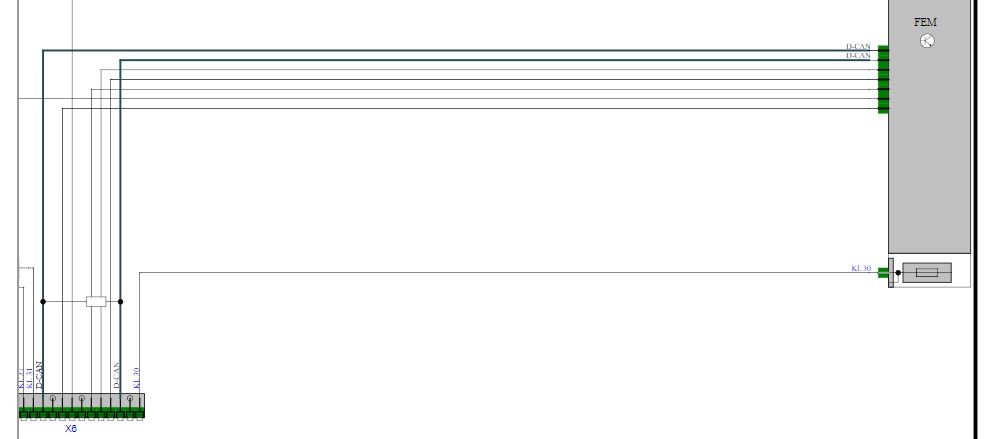 OBD2 port wiring diagram
6. What Tools Do You Need to Diagnose No Power to OBD2?
The essential tools include a multimeter, a scan tool, a fuse tester, a wiring diagram for your vehicle, and basic hand tools like screwdrivers and pliers.
For effective diagnosis, it’s essential to have the right tools:
- Multimeter: A multimeter is indispensable for testing voltage, continuity, and resistance. According to Fluke Corporation, a leading manufacturer of multimeters, a good quality multimeter should have an accuracy of at least 0.5% DC voltage.
- Scan Tool: A scan tool is needed to read diagnostic trouble codes (DTCs) and monitor live data. Modern scan tools can also perform advanced functions such as module programming and bi-directional testing.
- Fuse Tester: A fuse tester quickly checks the integrity of fuses without removing them.
- Wiring Diagram: A wiring diagram specific to your vehicle model is crucial for tracing circuits and identifying connection points. Websites like ALLDATA and Mitchell 1 offer comprehensive wiring diagrams.
- Basic Hand Tools: Screwdrivers, pliers, wire strippers, and other basic hand tools are needed for accessing and manipulating wiring and components.
7. How to Use a Multimeter to Check for Power and Ground?
To check for power, set the multimeter to DC voltage, connect the black lead to a known good ground, and the red lead to the power pin on the OBD2 port (usually pin 16). You should see approximately 12V. To check for ground, set the multimeter to continuity, connect one lead to a known good ground, and the other to the ground pin on the OBD2 port (usually pin 4 or 5). The multimeter should show continuity.
Here’s a step-by-step guide:
- Set the Multimeter:
- For checking power, set the multimeter to DC voltage (usually marked as “VDC” or “DCV”).
- For checking ground, set the multimeter to continuity mode (usually marked with a sound wave symbol).
- Check for Power:
- Locate pin 16 on the OBD2 port, which is the power supply pin.
- Connect the black lead of the multimeter to a known good ground on the vehicle, such as a clean, unpainted metal surface on the chassis.
- Connect the red lead of the multimeter to pin 16 on the OBD2 port.
- Turn the ignition to the “ON” position (but do not start the engine).
- Observe the multimeter reading. You should see approximately 12 volts. If the reading is significantly lower or zero, there is a power supply issue.
- Check for Ground:
- Locate the ground pins on the OBD2 port, typically pins 4 and 5.
- Connect one lead of the multimeter to a known good ground on the vehicle.
- Connect the other lead to either pin 4 or pin 5 on the OBD2 port.
- The multimeter should beep or display a low resistance value, indicating continuity between the ground pin and the vehicle’s ground. If there is no continuity, there is a grounding issue.
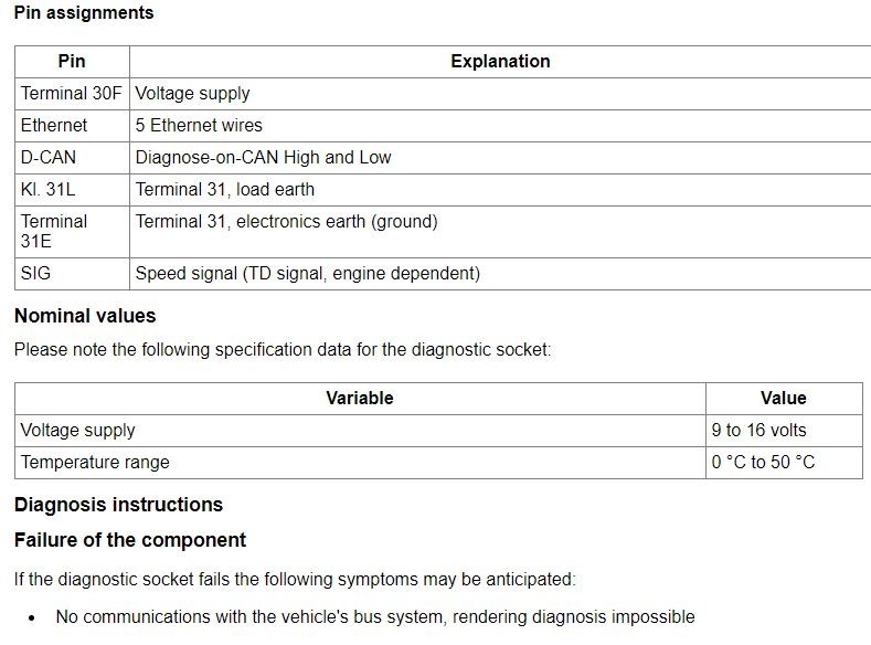
8. What is the OBD2 Port Pinout Diagram?
The OBD2 port pinout diagram is a reference chart that shows the function of each pin in the OBD2 port. Common pins include power (pin 16), ground (pins 4 and 5), and various communication lines like CAN High (pin 6) and CAN Low (pin 14).
The OBD2 port pinout diagram is crucial for diagnosing electrical issues and ensuring proper connections. Here is a table outlining the typical functions of the most common OBD2 port pins:
| Pin Number | Function | Description |
|---|---|---|
| 2 | SAE J1850 Line | Used for older vehicles; may be VPW (Variable Pulse Width) or PWM (Pulse Width Modulation). |
| 4 | Chassis Ground | Provides a ground connection to the vehicle’s chassis. |
| 5 | Signal Ground | Provides a ground reference for the diagnostic signals. |
| 6 | CAN High (J-2284) | Carries the high signal for the Controller Area Network (CAN) bus, used for communication between modules. |
| 7 | ISO 9141-2 K Line | Used for ISO 9141-2 communication; often used in European vehicles. |
| 10 | SAE J1850 Line | Used for older vehicles; may be VPW (Variable Pulse Width) or PWM (Pulse Width Modulation). |
| 14 | CAN Low (J-2284) | Carries the low signal for the Controller Area Network (CAN) bus, used for communication between modules. |
| 15 | ISO 9141-2 L Line | Used for ISO 9141-2 communication; often used in European vehicles. |
| 16 | Battery Power (12V) | Supplies power to the scan tool; should read approximately 12V when the ignition is on. |
9. How to Check for Short Circuits in the Wiring?
To check for short circuits, disconnect the battery, set the multimeter to continuity, and check for continuity between the OBD2 pins and ground. Any continuity indicates a short circuit.
Checking for short circuits in the wiring is a critical step in diagnosing power issues. Here’s a detailed guide:
- Disconnect the Battery:
- Before beginning any electrical testing, disconnect the negative terminal of the vehicle’s battery to prevent electrical shock and avoid damaging the vehicle’s electrical system.
- Set the Multimeter:
- Set the multimeter to continuity mode (usually indicated by a sound wave symbol).
- Check for Continuity to Ground:
- Connect one lead of the multimeter to a known good ground on the vehicle, such as a clean, unpainted metal surface on the chassis.
- Touch the other lead to each pin on the OBD2 port, one at a time.
- If the multimeter beeps or displays a low resistance value on any pin other than the designated ground pins (typically pins 4 and 5), there is a short circuit to ground on that pin’s circuit.
- Isolate the Short:
- If a short circuit is detected, consult the vehicle’s wiring diagram to trace the circuit connected to the affected pin.
- Inspect the wiring along the circuit for any signs of damage, such as frayed wires, melted insulation, or corrosion.
- Disconnect connectors along the circuit to isolate the short. When the short disappears, the problem lies in the section of wiring or component that was just disconnected.
- Repair the Short:
- Once the short circuit is located, repair the wiring or replace the faulty component.
- Ensure that all connections are properly insulated and protected to prevent future shorts.
- Reconnect the Battery:
- After repairing the short circuit, reconnect the negative terminal of the vehicle’s battery.
- Test the System:
- Test the OBD2 port with a scan tool to ensure that power has been restored and that there are no remaining issues.
10. How to Diagnose a Faulty ECU?
Diagnosing a faulty ECU (Engine Control Unit) requires advanced techniques, including checking for proper power and ground at the ECU, inspecting the ECU for physical damage, and using a scan tool to check for ECU-specific diagnostic codes.
Here’s a structured approach:
- Check ECU Power and Ground:
- Locate the ECU and identify the power and ground pins using a wiring diagram.
- Use a multimeter to check for proper voltage (typically 12V) at the power pins and continuity to ground at the ground pins.
- If there is no power or ground, trace the wiring back to the power source or ground point to identify any breaks or shorts.
- Inspect the ECU for Physical Damage:
- Visually inspect the ECU for any signs of physical damage, such as burnt components, corrosion, or water damage.
- Check the ECU connectors for bent or corroded pins.
- Check for ECU-Specific Diagnostic Codes:
- Connect a scan tool to the OBD2 port and check for diagnostic trouble codes (DTCs) related to the ECU.
- Pay attention to codes that indicate internal ECU faults, communication errors, or sensor failures.
- Perform ECU Reset or Reprogramming:
- Some ECU issues can be resolved by performing a reset or reprogramming the ECU.
- Use a scan tool with reprogramming capabilities to flash the ECU with the latest software.
11. What is the Role of the Front Electronics Module (FEM)?
The Front Electronics Module (FEM) in vehicles, particularly BMWs, controls various electronic functions, including power distribution to the OBD2 port. Issues with the FEM can result in no power to the OBD2 port.
The FEM is a critical component in modern vehicles, especially those from BMW. According to BMW technical documentation, the FEM integrates several functions, including:
- Power Distribution: The FEM manages the distribution of power to various vehicle systems, including the OBD2 port.
- Lighting Control: The FEM controls the vehicle’s exterior and interior lighting.
- Central Locking: The FEM manages the central locking system, including remote key functions.
- Alarm System: The FEM integrates the vehicle’s alarm system, providing anti-theft protection.
If the FEM is malfunctioning, it can lead to various issues, including no power to the OBD2 port. Causes of FEM malfunctions include:
- Software Issues: Corrupted or outdated software can cause the FEM to malfunction.
- Hardware Failures: Component failures within the FEM can disrupt its normal operation.
- Wiring Problems: Damaged or corroded wiring can prevent the FEM from functioning correctly.
12. How Can a Weak Battery Affect the OBD2 Port?
A weak battery can prevent the OBD2 port from functioning because the port requires a stable voltage to operate correctly. A low voltage can cause the diagnostic tool to fail to power on or communicate with the vehicle’s computer.
A weak or failing battery can have a cascading effect on various vehicle systems, including the OBD2 port. The OBD2 port requires a stable voltage supply to function correctly. According to a study by the Battery Council International (BCI), a voltage drop below 11.5 volts can cause electronic modules to malfunction.
Here’s how a weak battery can affect the OBD2 port:
- Insufficient Voltage: A weak battery may not provide the necessary voltage to power the OBD2 port and the connected scan tool.
- Communication Errors: Low voltage can disrupt the communication between the scan tool and the vehicle’s computer, resulting in error messages.
- Module Malfunctions: Other electronic modules in the vehicle may also malfunction due to low voltage, further complicating the diagnostic process.
13. What is a Terminating Resistor and Why Is It Important?
A terminating resistor, typically 120 ohms, is installed between pins 6 and 14 of the OBD2 port to ensure proper communication on the CAN bus. This resistor prevents signal reflections and ensures data integrity.
The terminating resistor is a critical component in the Controller Area Network (CAN) bus system, which is used for communication between various electronic modules in modern vehicles. Here’s why it’s important:
- Signal Integrity: The terminating resistor prevents signal reflections on the CAN bus, ensuring that data is transmitted and received accurately.
- Impedance Matching: The resistor matches the impedance of the CAN bus, minimizing signal distortion and ensuring reliable communication.
- Network Stability: Without a terminating resistor, the CAN bus can become unstable, leading to communication errors and diagnostic issues.
According to Bosch, a leading supplier of automotive electronics, a 120-ohm terminating resistor is typically installed at each end of the CAN bus to ensure proper signal termination.
14. What Is the Engine Speed Signal and How Does It Relate to the OBD2 Port?
The engine speed signal, connected to pin 9 on some vehicles, provides the diagnostic tool with information about the engine’s RPM. This signal helps in diagnosing engine-related issues and monitoring performance.
The engine speed signal, often referred to as RPM (Revolutions Per Minute), is a critical parameter for diagnosing engine-related issues and monitoring overall vehicle performance. Here’s how it relates to the OBD2 port:
- Real-Time Data: The engine speed signal is transmitted to the OBD2 port, allowing technicians to monitor the engine’s RPM in real-time using a scan tool.
- Diagnostic Information: The engine speed signal is used by the vehicle’s computer to calculate various parameters, such as fuel consumption, ignition timing, and emission levels.
- Troubleshooting: By monitoring the engine speed signal, technicians can diagnose issues such as misfires, idle problems, and performance-related faults.
15. Why Is There a Need for an Ethernet Connection in Some OBD2 Ports?
An Ethernet connection in some OBD2 ports is necessary for high-speed data transfer, especially in newer vehicles that require faster communication for advanced diagnostics and programming.
In modern vehicles, the amount of data that needs to be transmitted and processed has increased significantly. Traditional communication protocols, such as CAN bus, may not be sufficient to handle the bandwidth requirements of advanced systems.
Here’s why an Ethernet connection is needed in some OBD2 ports:
- High-Speed Data Transfer: Ethernet provides a much faster data transfer rate compared to traditional protocols, allowing for quicker diagnostics and programming.
- Advanced Diagnostics: Modern vehicles have complex electronic systems that require high-speed communication for tasks such as module programming, software updates, and advanced diagnostics.
- Future-Proofing: As vehicle technology continues to evolve, Ethernet connections will become increasingly important for supporting new features and functionalities.
16. What Steps Should You Take After Checking Fuses and Wiring?
After checking fuses and wiring, and if the problem persists, verify power and ground at the FEM, check for other related symptoms, and consider the possibility of a faulty OBD2 port or ECU.
Even after checking the fuses and wiring, you may still encounter the frustrating “no power to OBD2 port” issue. Here’s what to do next:
-
Verify Power and Ground at the FEM:
- Use a multimeter to check for proper voltage and ground at the Front Electronics Module (FEM).
- Consult the wiring diagram to identify the power and ground pins for the FEM.
- If there is no power or ground at the FEM, trace the wiring back to the power source or ground point to identify any breaks or shorts.
-
Check for Other Related Symptoms:
- Are there any other electrical issues in the vehicle that may be related to the OBD2 port problem?
- Check for malfunctioning lights, sensors, or other electronic components.
- If there are other symptoms, they may provide clues as to the root cause of the issue.
-
Consider the Possibility of a Faulty OBD2 Port:
- The OBD2 port itself may be damaged or have corroded pins.
- Visually inspect the port for any signs of damage.
- Use a terminal cleaning tool to clean the pins and ensure good contact.
- If necessary, replace the OBD2 port with a new one.
-
Consider the Possibility of a Faulty ECU:
- While less common, a malfunctioning Engine Control Unit (ECU) can cause the OBD2 port to lose power.
- Check for ECU-specific diagnostic trouble codes (DTCs) using a scan tool.
- If necessary, consult a professional technician for ECU testing and repair.
17. How to Handle Intermittent Power Loss to the OBD2 Port?
Handling intermittent power loss involves checking for loose connections, corrosion, and temperature-related issues. Monitor the system under various conditions to identify the cause.
Intermittent power loss to the OBD2 port can be particularly challenging to diagnose. Here’s how to approach it:
- Check for Loose Connections:
- Inspect all wiring connections related to the OBD2 port, including those at the fuse box, FEM, ECU, and the port itself.
- Ensure that all connectors are properly seated and secured.
- Look for any signs of corrosion or damage.
- Check for Corrosion:
- Corrosion can cause intermittent electrical problems.
- Clean any corroded terminals or connectors with a wire brush or terminal cleaning solution.
- Apply dielectric grease to protect against future corrosion.
- Monitor the System Under Various Conditions:
- Try to identify the conditions under which the power loss occurs.
- Does it happen when the engine is hot or cold?
- Does it happen when the vehicle is moving or stationary?
- Does it happen when certain electrical loads are active (e.g., headlights, air conditioning)?
- Use a multimeter to monitor the voltage at the OBD2 port while recreating the conditions that trigger the power loss.
- Check Temperature-Related Issues:
- Temperature changes can affect the resistance of wiring and components, leading to intermittent problems.
- Use a heat gun or cold spray to selectively heat or cool components and wiring while monitoring the OBD2 port voltage.
- If the power loss occurs when a particular component is heated or cooled, it may indicate a temperature-related issue.
18. What Are Some Common Mistakes to Avoid When Diagnosing No Power to OBD2?
Common mistakes include not checking the basics (like fuses), using the wrong tools, misinterpreting wiring diagrams, and failing to consider other related symptoms.
Diagnosing electrical issues can be complex, and it’s easy to make mistakes if you’re not careful. Here are some common mistakes to avoid when diagnosing no power to the OBD2 port:
- Not Checking the Basics:
- Always start with the simplest checks, such as fuses and wiring connections.
- Don’t assume that the problem is complex without first ruling out the obvious causes.
- Using the Wrong Tools:
- Using the wrong tools can lead to inaccurate readings and further damage.
- Make sure you have the right tools for the job, such as a multimeter, scan tool, fuse tester, and wiring diagram.
- Misinterpreting Wiring Diagrams:
- Wiring diagrams can be complex and difficult to understand.
- Take the time to study the wiring diagram carefully and make sure you understand the symbols and conventions.
- If you’re not sure, consult a professional technician for assistance.
- Failing to Consider Other Related Symptoms:
- The OBD2 port problem may be related to other electrical issues in the vehicle.
- Check for malfunctioning lights, sensors, or other electronic components.
- These symptoms may provide clues as to the root cause of the issue.
- Not Disconnecting the Battery:
- Always disconnect the negative terminal of the vehicle’s battery before performing any electrical testing.
- This will prevent electrical shock and avoid damaging the vehicle’s electrical system.
- Using the Wrong Fuse:
- Always replace a blown fuse with a new one of the exact same amperage.
- Using a fuse with a higher amperage can cause serious damage to your vehicle’s electrical system.
- Overlooking Corrosion:
- Corrosion can cause intermittent electrical problems.
- Clean any corroded terminals or connectors with a wire brush or terminal cleaning solution.
- Apply dielectric grease to protect against future corrosion.
19. When Should You Consult a Professional?
Consult a professional when you’re not comfortable working with electrical systems, if you can’t find the problem after basic checks, or if the issue involves complex systems like the ECU or FEM.
While many OBD2 port issues can be resolved with basic troubleshooting, there are times when it’s best to consult a professional technician. Here are some situations where you should seek expert assistance:
-
Not Comfortable Working with Electrical Systems:
- Working with electrical systems can be dangerous if you’re not properly trained.
- If you’re not comfortable performing electrical tests or repairs, it’s best to leave it to a professional.
-
Can’t Find the Problem After Basic Checks:
- If you’ve checked the fuses, wiring, and other basic components and still can’t find the problem, it may be a more complex issue.
- A professional technician has the tools and expertise to diagnose and repair difficult problems.
-
Issue Involves Complex Systems:
- Issues involving complex systems like the ECU or FEM require specialized knowledge and equipment.
- Attempting to repair these systems without the proper training can cause further damage.
-
Intermittent Problems:
- Intermittent electrical problems can be particularly challenging to diagnose.
- A professional technician has the tools and experience to track down intermittent issues and identify the root cause.
20. What Advanced Diagnostic Techniques Can a Professional Technician Use?
Professional technicians use advanced techniques such as oscilloscope testing, ECU reprogramming, and specialized scan tools to diagnose complex electrical issues.
Professional technicians have access to advanced diagnostic tools and techniques that can help them diagnose complex electrical issues more efficiently. Here are some examples:
- Oscilloscope Testing:
- An oscilloscope is an electronic instrument that displays electrical signals as waveforms.
- Technicians can use an oscilloscope to analyze the signals on the CAN bus, identify signal distortions, and diagnose communication issues.
- ECU Reprogramming:
- ECU reprogramming involves flashing the ECU with updated software or custom calibrations.
- Technicians can use ECU reprogramming to fix software glitches, improve performance, and address drivability issues.
- Specialized Scan Tools:
- Professional-grade scan tools have advanced features such as bi-directional control, module programming, and access to OEM diagnostic data.
- These scan tools can help technicians diagnose complex electrical issues more quickly and accurately.
- Network Analysis:
- Technicians can use network analysis tools to monitor the communication between different modules in the vehicle.
- This can help identify communication errors, bus conflicts, and other network-related issues.
- Thermal Imaging:
- Thermal imaging cameras can be used to identify hot spots or cold spots in electrical circuits.
- This can help technicians locate shorts, opens, and other electrical problems.
21. How to Prevent Future Issues with the OBD2 Port?
Preventive measures include regular inspections, protecting the port from damage, and ensuring proper maintenance of your vehicle’s electrical system.
Preventing future issues with the OBD2 port involves a combination of regular maintenance, careful usage, and protective measures. Here are some tips to keep your OBD2 port in good working condition:
- Regular Inspections:
- Periodically inspect the OBD2 port and its wiring for any signs of damage, corrosion, or loose connections.
- Address any issues promptly to prevent them from escalating.
- Protect the Port from Damage:
- Avoid bumping or jarring the OBD2 port, as this can damage the pins or wiring.
- When not in use, consider using a protective cover to prevent dust, dirt, and moisture from entering the port.
- Ensure Proper Maintenance of Your Vehicle’s Electrical System:
- Keep your vehicle’s battery in good condition.
- Address any electrical issues promptly to prevent them from affecting the OBD2 port.
- Use High-Quality Scan Tools and Adapters:
- When using a scan tool or adapter, make sure it is of high quality and compatible with your vehicle.
- Poorly made scan tools or adapters can damage the OBD2 port or the vehicle’s computer.
- Avoid Overloading the Circuit:
- Do not plug multiple devices into the OBD2 port at the same time, as this can overload the circuit and blow a fuse.
- Keep the Port Clean:
- Use a terminal cleaning tool or a cotton swab to gently clean the pins of the OBD2 port.
- Apply dielectric grease to protect against corrosion.
22. What Are the Benefits of Using CAR-DIAGNOSTIC-TOOL.EDU.VN Resources?
Using CAR-DIAGNOSTIC-TOOL.EDU.VN provides access to expert guides, diagnostic tools, and comprehensive repair solutions, ensuring efficient and accurate vehicle maintenance.
At CAR-DIAGNOSTIC-TOOL.EDU.VN, we understand the challenges technicians and vehicle owners face when diagnosing and repairing modern vehicles. That’s why we offer a comprehensive suite of resources designed to make your job easier and more efficient. Here are some of the benefits of using our resources:
-
Expert Guides:
- We provide detailed, step-by-step guides on diagnosing and repairing a wide range of vehicle issues, including no power to the OBD2 port.
- Our guides are written by experienced technicians and are regularly updated to reflect the latest technology and best practices.
-
Diagnostic Tools:
- We offer a wide selection of high-quality diagnostic tools, including scan tools, multimeters, fuse testers, and wiring diagrams.
- Our tools are designed to help you quickly and accurately diagnose vehicle problems.
-
Comprehensive Repair Solutions:
- We provide comprehensive repair solutions for a wide range of vehicle issues.
- Our solutions include detailed repair procedures, parts lists, and technical support.
-
Remote Support:
- We offer remote support services to help you troubleshoot complex issues and get your vehicle back on the road quickly.
- Our remote support team is staffed by experienced technicians who can provide expert guidance and assistance.
-
Technical Training:
- We offer technical training courses to help you improve your skills and knowledge.
- Our courses cover a wide range of topics, including diagnostics, repair procedures, and advanced vehicle technology.
By using CAR-DIAGNOSTIC-TOOL.EDU.VN resources, you can save time, reduce costs, and improve the quality of your work. We are committed to providing you with the tools and knowledge you need to succeed in the automotive industry.
23. How Can Remote Support Assist with OBD2 Port Issues?
Remote support offers real-time assistance from experienced technicians, guiding you through diagnostic steps, interpreting data, and providing solutions for OBD2 port problems.
Remote support can be a valuable resource for diagnosing and resolving OBD2 port issues, especially when you’re facing complex or challenging problems. Here’s how remote support can assist you:
-
Real-Time Guidance:
- Remote support provides real-time assistance from experienced technicians who can guide you through the diagnostic process.
- They can help you identify the right steps to take, interpret the data from your scan tool, and troubleshoot potential issues.
-
Expert Knowledge:
- Remote support technicians have in-depth knowledge of vehicle electrical systems and diagnostic procedures.
- They can provide expert insights and recommendations that may not be readily available in repair manuals or online forums.
-
Access to Advanced Tools:
- Remote support technicians have access to advanced diagnostic tools and resources, such as wiring diagrams, technical service bulletins (TSBs), and OEM diagnostic data.
- They can use these tools to help you diagnose complex issues more quickly and accurately.
-
Troubleshooting Complex Issues:
- Remote support can be particularly helpful for troubleshooting complex or intermittent issues.
- Technicians can help you analyze the data from your scan tool, monitor the system in real-time, and identify potential causes of the problem.
-
Time and Cost Savings:
- Remote support can save you time and money by helping you diagnose and resolve issues more quickly.
- You can avoid unnecessary repairs and parts replacements by getting expert guidance from a remote technician.
24. What are the Key Topics Covered in Technical Training Courses?
Technical training courses cover essential topics such as electrical diagnostics, CAN bus systems, ECU programming, and advanced troubleshooting techniques, enhancing your diagnostic skills.
Technical training courses are essential for technicians who want to stay up-to-date with the latest automotive technology and improve their diagnostic skills. Here are some key topics that are typically covered in these courses:
-
Electrical Diagnostics:
- Electrical diagnostics courses cover the fundamentals of electricity, wiring diagrams, and electrical testing procedures.
- Technicians learn how to use multimeters, oscilloscopes, and other diagnostic tools to troubleshoot electrical issues.
-
CAN Bus Systems:
- CAN bus systems courses cover the principles of Controller Area Network (CAN) communication, network architecture, and diagnostic procedures.
- Technicians learn how to diagnose CAN bus issues, such as communication errors, bus conflicts, and wiring problems.
-
ECU Programming:
- ECU programming courses cover the basics of Engine Control Unit (ECU) programming, software updates, and calibration procedures.
- Technicians learn how to use scan tools and other programming devices to reprogram ECUs and address drivability issues.
-
Advanced Troubleshooting Techniques:
- Advanced troubleshooting courses cover a variety of advanced diagnostic techniques, such as oscilloscope testing, network analysis, and thermal imaging.
- Technicians learn how to use these techniques to diagnose complex and intermittent issues.
-
Hybrid and Electric Vehicle Technology:
- Hybrid and electric vehicle (EV) technology courses cover the principles of hybrid and EV operation, high-voltage safety procedures, and diagnostic techniques.
- Technicians learn how to safely work on hybrid and EV vehicles and diagnose issues related to the high-voltage systems.