Is your OBD2 scanner not connecting to your vehicle? CAR-DIAGNOSTIC-TOOL.EDU.VN offers expert insights into why your scan tool might fail to communicate, providing detailed troubleshooting steps and solutions to get you back on track with accurate vehicle diagnostics. We also offer advanced remote support and technician training to help you further diagnose and resolve issues.
Contents
- 1. What Causes an OBD2 Scanner to Fail Connection?
- 2. How Do I Troubleshoot a Non-Connecting OBD2 Scanner?
- 2.1. Check the OBD2 Scanner
- 2.2. Inspect the OBD2 Port
- 2.3. Verify Vehicle’s Electrical System
- 3. What are the Key Tests to Diagnose OBD2 Connection Issues?
- 3.1. Ground Resistance Test (DLC Pins 4 and 5)
- 3.2. Voltage Check on DLC Pin 2 (Class 2 Serial Data)
- 3.3. ECM Voltage Supply Test
- 3.4. DLC Bias Terminal Voltage Test
- 4. What Does It Mean If the PCM Is Not Entering Diagnostic Mode?
- 5. How Do Wiring Issues Affect OBD2 Scanner Connections?
- 6. Can a Dead Battery Prevent an OBD2 Scanner from Connecting?
- 7. How Do I Check the Voltage Supply to the ECM?
- 8. What Role Does the Fuse Box Play in OBD2 Connections?
- 9. What is the Significance of Bus Activity in DLC Terminal Voltage Tests?
- 10. How Can CAR-DIAGNOSTIC-TOOL.EDU.VN Assist with OBD2 Connection Problems?
- 11. What is the Role of the Powertrain Control Module (PCM)?
- 12. What Happens if the PCM Is Damaged or Fried?
- 13. How to Check the Continuity of the OBD2 Port Pins?
- 14. How do Faulty CAN Bus Affect the OBD2 Scanner?
- 15. How Do I Resolve a “No Communication” Error with an OBD2 Scanner?
- 16. What are the Common OBD2 Connector Pinouts and Their Functions?
- 17. How Does the Vehicle’s Computer System Interact with the OBD2 Scanner?
- 18. What Training Does CAR-DIAGNOSTIC-TOOL.EDU.VN Offer?
- 19. How to Use a Digital Multimeter (DMM) for OBD2 Diagnostics?
- 20. What Are the Benefits of Remote Diagnostic Support from CAR-DIAGNOSTIC-TOOL.EDU.VN?
- FAQ Section
1. What Causes an OBD2 Scanner to Fail Connection?
An OBD2 scanner might fail to connect due to several reasons, including a faulty scanner, a damaged OBD2 port, wiring issues, or a dead battery. Identifying the root cause is the first step toward resolving the connection problem.
- Faulty Scanner: The scanner itself may have hardware or software malfunctions that prevent it from establishing a connection.
- Damaged OBD2 Port: The port in your vehicle could be physically damaged or have corroded pins, leading to connection failures.
- Wiring Issues: Damaged or disconnected wires between the OBD2 port and the vehicle’s computer can interrupt communication.
- Dead Battery: A severely discharged vehicle battery can prevent the scanner from powering on or communicating effectively.
2. How Do I Troubleshoot a Non-Connecting OBD2 Scanner?
To troubleshoot a non-connecting OBD2 scanner, start by checking the scanner, the OBD2 port, and the vehicle’s electrical system. Use a multimeter to test for power and continuity in the relevant circuits.
2.1. Check the OBD2 Scanner
- Ensure Compatibility: Verify that the scanner is compatible with your vehicle’s make, model, and year.
- Test on Another Vehicle: If possible, test the scanner on a known working vehicle to rule out internal scanner issues.
- Software Updates: Ensure the scanner’s software is up to date to support the latest protocols and vehicle models.
2.2. Inspect the OBD2 Port
- Visual Inspection: Look for any signs of physical damage, such as bent or broken pins.
- Clean the Port: Use a contact cleaner to remove any corrosion or debris from the pins.
- Pin Continuity: Use a multimeter to check the continuity of the pins, ensuring they are correctly connected to the vehicle’s wiring.
2.3. Verify Vehicle’s Electrical System
- Battery Voltage: Check the battery voltage to ensure it meets the minimum requirements for the scanner to operate. A fully charged battery should read around 12.6 volts.
- Fuse Check: Inspect the fuses related to the OBD2 port and the vehicle’s computer system. Replace any blown fuses.
3. What are the Key Tests to Diagnose OBD2 Connection Issues?
Several tests can help diagnose OBD2 connection issues, including ground resistance tests, voltage checks on the DLC pins, and verifying the ECM’s power supply.
3.1. Ground Resistance Test (DLC Pins 4 and 5)
Procedure:
- Connect the positive lead of a digital multimeter (DMM) to DLC pin 4.
- Connect the negative lead of the DMM to the negative battery terminal. Use jumper wires if necessary, ensuring a direct connection to the battery terminal, not the chassis ground.
- Turn on the ignition.
- Measure the voltage drop across the ground terminal. It should be 0.1 volts or less.
- Repeat the procedure for DLC pin 5.
Note: High ground resistance or an open circuit can prevent the PCM from entering diagnostic mode.
3.2. Voltage Check on DLC Pin 2 (Class 2 Serial Data)
Note: This test is not applicable to Mazda MPV vehicles.
Procedure:
- Connect the positive lead of the DMM to the Class 2 Serial Data pin (DLC pin 2).
- Connect the negative lead to either pin 4, pin 5, or a known good ground.
- Turn on the ignition.
- Measure the voltage. It should be 5V or fluctuate between 3.5V and 5.0V.
Note: An open circuit on this pin will prevent the PCM from transmitting data to the scan tool.
3.3. ECM Voltage Supply Test
Procedure:
- Connect the positive lead of the DMM to the positive terminal of the DLC (Battery + terminal).
- Connect the negative lead of the DMM to the battery ground terminal.
- Measure the voltage. It should read the battery voltage.
Note: This test verifies that the ECM is receiving adequate power. A blown lighter fuse may cause a lack of power.
3.4. DLC Bias Terminal Voltage Test
Procedure:
- Connect the positive lead of the DMM to either of the DLC bias terminals.
- Connect the negative lead to the ground terminal.
- Turn the ignition key ON.
- Without bus activity, the BUS + should read 0V, and the BUS – should read 5V.
- With bus activity, the voltage should vary from 0 to 5V, depending on the level of bus activity.
Note: These readings can help identify issues with the data bus communication.
4. What Does It Mean If the PCM Is Not Entering Diagnostic Mode?
If the PCM (Powertrain Control Module) is not entering diagnostic mode, it typically indicates a problem with the ground circuit or high resistance in the system, preventing proper communication.
- Faulty Ground Connection: An open circuit or high resistance in the ground circuit will prevent the PCM from functioning correctly.
- Power Supply Issues: The PCM requires a stable power supply to operate. Check for blown fuses or issues with the ECM voltage supply.
- Data Bus Problems: Issues with the CAN (Controller Area Network) bus can also prevent the PCM from entering diagnostic mode.
5. How Do Wiring Issues Affect OBD2 Scanner Connections?
Wiring issues, such as disconnected or damaged wires, can severely affect OBD2 scanner connections by interrupting the flow of data and power.
- Disconnected Wires: Loose or disconnected wires can prevent the scanner from receiving power or data.
- Damaged Wires: Frayed, corroded, or broken wires can cause signal loss or short circuits.
- Short Circuits: A short circuit in the wiring can cause the scanner to malfunction or the vehicle’s computer to reset.
6. Can a Dead Battery Prevent an OBD2 Scanner from Connecting?
Yes, a dead or severely low battery can prevent an OBD2 scanner from connecting. The scanner requires a certain voltage level to power on and communicate with the vehicle’s computer.
- Insufficient Voltage: If the battery voltage is too low, the scanner may not power on or may not be able to establish a reliable connection.
- Battery Drain: A faulty battery can drain quickly, especially when the ignition is turned on for diagnostic purposes.
- Voltage Drop During Scan: The battery voltage may drop further during the scan, causing intermittent connection issues.
7. How Do I Check the Voltage Supply to the ECM?
Checking the voltage supply to the ECM (Engine Control Module) involves using a digital multimeter (DMM) to measure the voltage at the appropriate terminals.
Procedure:
- Locate the ECM: Find the ECM in your vehicle, usually located under the dashboard, under the seats, or in the engine compartment. Consult your vehicle’s service manual for the exact location.
- Identify the Power and Ground Terminals: Refer to the wiring diagram for your vehicle to identify the power (B+) and ground terminals on the ECM connector.
- Set Up the Multimeter: Set your DMM to the DC voltage setting.
- Connect the Leads:
- Connect the positive lead of the DMM to the power (B+) terminal of the ECM connector.
- Connect the negative lead of the DMM to the ground terminal of the ECM connector or a known good ground.
- Measure the Voltage: Turn the ignition key to the “ON” position (do not start the engine). Read the voltage on the DMM. It should be close to the battery voltage (approximately 12.6 volts).
- Check for Voltage Drop: Start the engine and check the voltage again. It should remain relatively stable and not drop significantly (less than 0.5 volts).
- Interpret the Results:
- If the voltage is significantly lower than the battery voltage, there may be a voltage drop due to a corroded connection, a damaged wire, or a blown fuse.
- If there is no voltage, check the fuses and wiring leading to the ECM.
Note: According to FS1 Inc., the PCM receives battery voltage (B+) through a fuse or fusible link. An open ground or power circuit on a fuel-injected engine removes power from the ECM and prevents the engine from starting.
8. What Role Does the Fuse Box Play in OBD2 Connections?
The fuse box plays a crucial role in OBD2 connections by protecting the electrical circuits of the vehicle, including those related to the OBD2 port and the ECM.
- Protection of Circuits: Fuses protect the vehicle’s electrical components from overcurrent or short circuits.
- Power Supply to ECM and OBD2 Port: The ECM and OBD2 port rely on fuses to receive power. A blown fuse can interrupt the power supply, preventing the scanner from connecting.
- Diagnostic Step: Checking the fuse box is a vital diagnostic step when troubleshooting OBD2 connection issues.
9. What is the Significance of Bus Activity in DLC Terminal Voltage Tests?
Bus activity in DLC (Data Link Connector) terminal voltage tests indicates the level of communication occurring on the vehicle’s data bus. The voltage readings should vary between 0 and 5V, depending on the amount of bus activity.
- Communication Verification: Varying voltage readings confirm that data is being transmitted and received on the bus.
- Troubleshooting Tool: Absence of bus activity can indicate a problem with the data bus, ECM, or other modules connected to the bus.
- Diagnostic Indicator: The level of voltage variation can help diagnose the severity and nature of the communication problem.
10. How Can CAR-DIAGNOSTIC-TOOL.EDU.VN Assist with OBD2 Connection Problems?
CAR-DIAGNOSTIC-TOOL.EDU.VN provides comprehensive support for OBD2 connection problems, including remote assistance, detailed repair guides, and advanced technician training.
- Remote Support: Our expert technicians can provide real-time guidance to diagnose and resolve OBD2 connection issues remotely.
- Detailed Repair Guides: Access our extensive library of repair guides and troubleshooting procedures for various vehicle makes and models.
- Technician Training: Enroll in our advanced technician training programs to enhance your diagnostic skills and stay up-to-date with the latest automotive technologies.
 OBD2 scanner connected to a car
11. What is the Role of the Powertrain Control Module (PCM)?
The Powertrain Control Module (PCM) is the central control unit in a vehicle’s engine management system. It controls the engine, transmission, and other vital systems.
- Central Control Unit: The PCM processes data from various sensors and controls actuators to optimize engine performance, fuel efficiency, and emissions.
- Diagnostic Functions: The PCM stores diagnostic trouble codes (DTCs) and provides data to the OBD2 scanner for troubleshooting.
- Communication Hub: The PCM communicates with other modules in the vehicle, such as the ABS, SRS, and body control modules.
12. What Happens if the PCM Is Damaged or Fried?
If the PCM is damaged or fried, it can lead to numerous issues, including a no-start condition, poor engine performance, and communication problems with the OBD2 scanner.
- No-Start Condition: A damaged PCM may not provide the necessary signals to start the engine.
- Poor Engine Performance: Issues with the PCM can lead to rough idling, misfires, and reduced power.
- Communication Problems: A fried PCM may not communicate with the OBD2 scanner, preventing access to diagnostic information.
13. How to Check the Continuity of the OBD2 Port Pins?
Checking the continuity of the OBD2 port pins is essential to ensure they are properly connected to the vehicle’s wiring.
Procedure:
- Disconnect the Battery: Disconnect the negative terminal of the vehicle’s battery to prevent any electrical shorts during testing.
- Locate the OBD2 Port: Find the OBD2 port, typically located under the dashboard on the driver’s side.
- Identify the Pins: Refer to the OBD2 port pinout diagram to identify each pin’s function. Common pins to check include:
- Pin 4: Chassis Ground
- Pin 5: Signal Ground
- Pin 16: Battery Voltage (12V)
- Set Up the Multimeter: Set your multimeter to the continuity testing mode (usually indicated by a diode symbol or a sound wave symbol).
- Connect the Leads:
- Ground Pins (4 and 5):
- Connect one lead of the multimeter to pin 4 or pin 5.
- Connect the other lead to a known good ground point on the vehicle’s chassis.
- The multimeter should beep or display a low resistance value (close to 0 ohms), indicating continuity.
- Battery Voltage Pin (16):
- Connect one lead of the multimeter to pin 16.
- Connect the other lead to the positive terminal of the battery (with the battery still disconnected).
- The multimeter should beep or display a low resistance value, indicating continuity.
- Ground Pins (4 and 5):
- Check Other Pins (as needed): Check the continuity of other pins as needed, referring to the vehicle’s wiring diagram to identify their connections.
- Interpret the Results:
- Continuity: A beep or low resistance value indicates that the pin is properly connected to its corresponding circuit.
- No Continuity: If the multimeter does not beep or displays a high resistance value, there is a break in the circuit, indicating a wiring issue that needs to be addressed.
Note: Continuity testing should be performed with the battery disconnected to prevent any damage to the multimeter or vehicle electronics.
14. How do Faulty CAN Bus Affect the OBD2 Scanner?
A faulty CAN (Controller Area Network) bus can significantly affect the OBD2 scanner’s ability to communicate with the vehicle’s systems.
- Communication Disruption: The CAN bus is responsible for communication between the vehicle’s electronic control units (ECUs). If the CAN bus is faulty, it can disrupt the data flow, preventing the OBD2 scanner from receiving accurate information.
- Intermittent Connection: A faulty CAN bus can cause intermittent connection issues, where the OBD2 scanner connects and disconnects randomly.
- Inaccurate Data: Even if the OBD2 scanner connects, a faulty CAN bus can lead to inaccurate or incomplete data being displayed.
15. How Do I Resolve a “No Communication” Error with an OBD2 Scanner?
Resolving a “No Communication” error with an OBD2 scanner involves systematically checking the scanner, OBD2 port, vehicle wiring, and related components.
Troubleshooting Steps:
- Verify Scanner Compatibility: Ensure that the OBD2 scanner is compatible with the vehicle’s make, model, and year.
- Check OBD2 Port: Inspect the OBD2 port for damage, corrosion, or bent pins. Clean the port and straighten any bent pins.
- Test Scanner on Another Vehicle: Test the scanner on a known working vehicle to rule out scanner issues.
- Check Vehicle Battery: Ensure that the vehicle’s battery is fully charged. A low battery can prevent the scanner from connecting.
- Inspect Fuses: Check the fuses related to the OBD2 port and the ECM. Replace any blown fuses.
- Check Wiring: Inspect the wiring between the OBD2 port and the ECM for damage, corrosion, or loose connections.
- Perform Ground and Voltage Tests: Use a multimeter to check the ground resistance and voltage at the OBD2 port pins.
- Check CAN Bus: If possible, check the CAN bus for proper communication. Use an oscilloscope to analyze the CAN bus signals.
- PCM Issues: If all other components check out, the PCM may be faulty and require replacement.
- Update Scanner Software: Ensure the OBD2 scanner has the latest software updates installed.
Seeking Professional Assistance:
- If you are unable to resolve the “No Communication” error, consider seeking assistance from a qualified automotive technician.
- CAR-DIAGNOSTIC-TOOL.EDU.VN offers remote diagnostic support and technician training to help you resolve complex issues. Contact us at +1 (641) 206-8880 for expert assistance.
16. What are the Common OBD2 Connector Pinouts and Their Functions?
Understanding the OBD2 connector pinouts and their functions is crucial for effective troubleshooting.
Common OBD2 Connector Pinouts:
| Pin | Function | Description |
|---|---|---|
| 2 | J1850 Bus + | Used in older Ford vehicles |
| 4 | Chassis Ground | Ground connection for the vehicle chassis |
| 5 | Signal Ground | Ground connection for the signal circuits |
| 6 | CAN High (J-2284) | High signal line for the CAN bus |
| 7 | K-Line ISO 9141-2 | Used for communication in ISO 9141-2 protocol |
| 10 | J1850 Bus – | Used in older GM vehicles |
| 14 | CAN Low (J-2284) | Low signal line for the CAN bus |
| 15 | L-Line ISO 9141-2 | Used for communication in ISO 9141-2 protocol |
| 16 | Battery Power | Provides battery voltage to the OBD2 scanner |
Functions of Key Pins:
- Pin 4 (Chassis Ground): Provides a reliable ground connection to the vehicle’s chassis.
- Pin 5 (Signal Ground): Provides a ground connection for the signal circuits, ensuring accurate data transmission.
- Pin 6 (CAN High) and Pin 14 (CAN Low): These pins are part of the CAN bus, which allows various ECUs in the vehicle to communicate with each other.
- Pin 16 (Battery Power): Supplies power to the OBD2 scanner, allowing it to function.
Troubleshooting with Pinouts:
- Use a multimeter to check for proper voltage and continuity at each pin.
- Compare readings to the vehicle’s wiring diagram to identify any discrepancies.
- Ensure that each pin is securely connected to its corresponding wire.
17. How Does the Vehicle’s Computer System Interact with the OBD2 Scanner?
The vehicle’s computer system, particularly the Engine Control Module (ECM), interacts with the OBD2 scanner through a standardized set of protocols and diagnostic trouble codes (DTCs).
Interaction Process:
- Connection: The OBD2 scanner connects to the vehicle’s OBD2 port, establishing a physical link.
- Protocol Negotiation: The scanner and ECM negotiate a communication protocol (e.g., CAN, ISO 9141-2, J1850).
- Data Request: The scanner sends a request to the ECM for diagnostic information, such as DTCs, sensor data, and system status.
- Data Transmission: The ECM transmits the requested data back to the scanner.
- Data Display: The scanner displays the data in a user-friendly format, allowing technicians to diagnose issues.
Key Components:
- Engine Control Module (ECM): The main computer in the vehicle that controls engine functions and stores diagnostic information.
- OBD2 Port: The standardized port used to connect the scanner to the vehicle’s computer system.
- Communication Protocols: Standardized protocols that allow the scanner and ECM to communicate effectively.
- Diagnostic Trouble Codes (DTCs): Codes stored in the ECM that indicate specific issues or malfunctions.
18. What Training Does CAR-DIAGNOSTIC-TOOL.EDU.VN Offer?
CAR-DIAGNOSTIC-TOOL.EDU.VN offers a range of training programs designed to enhance the diagnostic skills of automotive technicians.
Training Programs:
- Basic Diagnostics: Introduction to automotive diagnostics, including the use of OBD2 scanners, multimeters, and other diagnostic tools.
- Advanced Diagnostics: In-depth training on diagnosing complex issues, including electrical system problems, CAN bus issues, and PCM failures.
- Engine Management Systems: Comprehensive training on engine management systems, including fuel injection, ignition, and emissions control.
- Remote Diagnostics: Learn how to provide remote diagnostic support to customers, using advanced tools and techniques.
- Customized Training: Tailored training programs to meet the specific needs of your team or organization.
Benefits of Training:
- Enhanced Skills: Improve your diagnostic skills and stay up-to-date with the latest automotive technologies.
- Increased Efficiency: Diagnose and repair vehicles more quickly and accurately.
- Improved Customer Satisfaction: Provide better service to your customers and increase their satisfaction.
- Career Advancement: Enhance your career prospects and become a certified automotive technician.
19. How to Use a Digital Multimeter (DMM) for OBD2 Diagnostics?
A digital multimeter (DMM) is an essential tool for diagnosing OBD2 connection issues. It can be used to check voltage, continuity, and resistance in the vehicle’s electrical circuits.
Basic Functions of a DMM:
- Voltage Measurement: Measures the voltage in DC or AC circuits.
- Continuity Testing: Checks for a complete circuit, indicating whether a connection is intact.
- Resistance Measurement: Measures the resistance in a circuit, indicating the level of opposition to current flow.
Using a DMM for OBD2 Diagnostics:
- Voltage Testing:
- Set the DMM to DC voltage mode.
- Connect the positive lead to the test point and the negative lead to a ground.
- Read the voltage on the DMM.
- Continuity Testing:
- Set the DMM to continuity mode.
- Disconnect power from the circuit being tested.
- Connect the leads to the two points being tested.
- If the DMM beeps or displays a low resistance value, there is continuity.
- Resistance Testing:
- Set the DMM to resistance mode.
- Disconnect power from the circuit being tested.
- Connect the leads to the two points being tested.
- Read the resistance value on the DMM.
Diagnostic Applications:
- Checking Battery Voltage: Ensure the battery is providing adequate voltage to the vehicle’s systems.
- Testing Fuses: Verify that fuses are intact and conducting electricity.
- Checking Wiring: Inspect the wiring for continuity and shorts.
- Testing Sensors: Measure the voltage and resistance of sensors to ensure they are functioning correctly.
20. What Are the Benefits of Remote Diagnostic Support from CAR-DIAGNOSTIC-TOOL.EDU.VN?
Remote diagnostic support from CAR-DIAGNOSTIC-TOOL.EDU.VN offers numerous benefits for automotive technicians and shop owners.
Benefits of Remote Support:
- Expert Assistance: Access to experienced technicians who can provide real-time guidance and support.
- Faster Diagnostics: Resolve issues more quickly and efficiently, reducing downtime.
- Cost Savings: Avoid the expense of hiring specialized technicians or purchasing expensive diagnostic equipment.
- Improved Customer Satisfaction: Provide better service to your customers and increase their satisfaction.
- Training and Education: Learn new diagnostic techniques and stay up-to-date with the latest automotive technologies.
How Remote Support Works:
- Contact Us: Reach out to CAR-DIAGNOSTIC-TOOL.EDU.VN at +1 (641) 206-8880 or visit our website at CAR-DIAGNOSTIC-TOOL.EDU.VN.
- Describe the Issue: Provide a detailed description of the problem you are experiencing.
- Connect Remotely: Our technicians will connect to your diagnostic equipment remotely.
- Receive Guidance: Receive real-time guidance and support to diagnose and resolve the issue.
FAQ Section
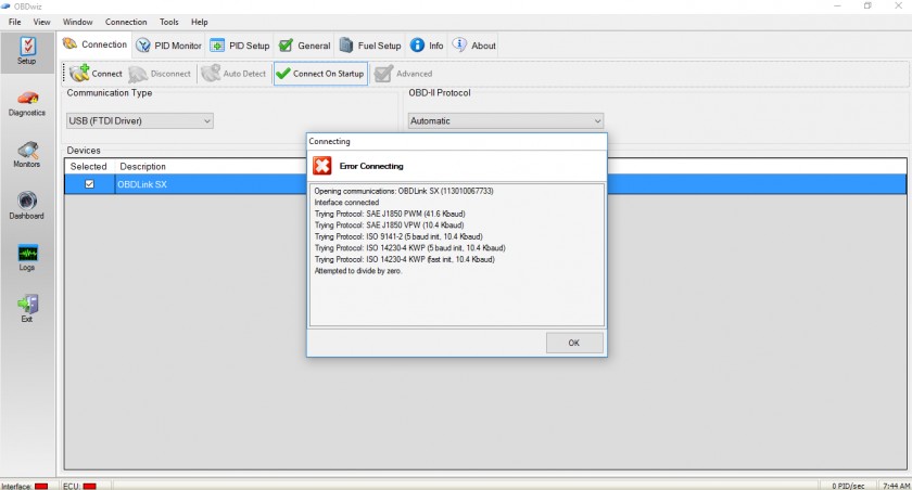
1. Why is my OBD2 scanner showing “No Link”?
A “No Link” message typically indicates that the scanner is unable to establish a connection with the vehicle’s computer. This could be due to a faulty scanner, damaged OBD2 port, wiring issues, or a dead battery.
2. How can I fix an OBD2 scanner that won’t connect?
Start by checking the scanner, the OBD2 port, and the vehicle’s electrical system. Use a multimeter to test for power and continuity in the relevant circuits. Ensure the scanner is compatible with your vehicle.
3. What does it mean if my PCM is not communicating?
If the PCM (Powertrain Control Module) is not communicating, it typically indicates a problem with the ground circuit, power supply, or data bus. This can prevent the OBD2 scanner from accessing diagnostic information.
4. Can a blown fuse cause OBD2 scanner connection problems?
Yes, a blown fuse can interrupt the power supply to the OBD2 port or ECM, preventing the scanner from connecting. Check the fuses related to the OBD2 port and the vehicle’s computer system.
5. How do I check the voltage supply to the OBD2 port?
Use a digital multimeter (DMM) to measure the voltage at pin 16 of the OBD2 port. With the ignition on, it should read close to the battery voltage (approximately 12.6 volts).
6. What is the role of the CAN bus in OBD2 communication?
The CAN (Controller Area Network) bus is responsible for communication between the vehicle’s electronic control units (ECUs). If the CAN bus is faulty, it can disrupt the data flow, preventing the OBD2 scanner from receiving accurate information.
7. How can CAR-DIAGNOSTIC-TOOL.EDU.VN help with remote diagnostics?
CAR-DIAGNOSTIC-TOOL.EDU.VN offers remote diagnostic support by connecting to your diagnostic equipment remotely and providing real-time guidance to diagnose and resolve issues.
8. What kind of training programs does CAR-DIAGNOSTIC-TOOL.EDU.VN offer for automotive technicians?
CAR-DIAGNOSTIC-TOOL.EDU.VN offers a range of training programs, including basic diagnostics, advanced diagnostics, engine management systems, remote diagnostics, and customized training programs.
9. What are the common OBD2 connector pinouts and their functions?
Common OBD2 connector pinouts include pin 4 (Chassis Ground), pin 5 (Signal Ground), pin 6 (CAN High), pin 14 (CAN Low), and pin 16 (Battery Power). Each pin has a specific function in the communication process.
10. How can I contact CAR-DIAGNOSTIC-TOOL.EDU.VN for assistance?
You can contact CAR-DIAGNOSTIC-TOOL.EDU.VN for assistance at +1 (641) 206-8880 or visit our website at CAR-DIAGNOSTIC-TOOL.EDU.VN. Our office is located at 1100 Congress Ave, Austin, TX 78701, United States.
Don’t let OBD2 connection issues slow you down. Contact CAR-DIAGNOSTIC-TOOL.EDU.VN today at +1 (641) 206-8880 or visit our website at CAR-DIAGNOSTIC-TOOL.EDU.VN for expert guidance, remote support, and comprehensive technician training. Our office is located at 1100 Congress Ave, Austin, TX 78701, United States. Let us help you enhance your diagnostic skills and stay ahead in the rapidly evolving automotive industry. Access our detailed repair guides, benefit from our remote assistance, and enroll in our training programs to master advanced diagnostic techniques.