The Obd2 Socket is your gateway to understanding your vehicle’s health. It’s a standardized port that allows access to diagnostic trouble codes (DTCs) and real-time data, and CAR-DIAGNOSTIC-TOOL.EDU.VN provides comprehensive tools, repair guides, and technical support to help you make the most of it. From technician training to remote assistance, CAR-DIAGNOSTIC-TOOL.EDU.VN is your one-stop resource for automotive diagnostics.
Contents
- 1. What is an OBD2 Socket?
- 1.1. Key Functions of the OBD2 Socket
- 1.2. Location of the OBD2 Socket
- 2. Does My Car Support OBD2?
- 2.1. How to Determine OBD2 Compliance
- 2.2. Exceptions and Special Cases
- 3. OBD2 History and Evolution
- 3.1. Key Milestones in OBD2 Development
- 3.2. The Role of Standard Organizations
- 4. The Future of OBD2: Trends and Innovations
- 4.1. OBD3 and Telematics
- 4.2. WWH-OBD and OBDonUDS
- 4.3. Challenges in the Era of Electric Vehicles
- 5. OBD2 Standards: SAE J1962 and ISO 15031-3
- 5.1. The OSI Model and OBD2 Standards
- 5.2. Key Differences Between SAE and ISO Standards
- 6. The OBD2 Connector: Pinout and Functionality
- 6.1. Pinout Diagram and Explanation
- 6.2. Type A vs. Type B Connectors
- 7. OBD2 and CAN Bus: ISO 15765-4
- 7.1. ISO 15765-4: Diagnostics Over CAN (DoCAN)
- 7.2. CAN Identifiers: 11-bit and 29-bit
- 7.3. OBD2 vs. Proprietary CAN Protocols
- 7.4. Bit-Rate and ID Validation
- 7.5. Five Lower-Layer OBD2 Protocols
- 8. Transporting OBD2 Messages via ISO-TP: ISO 15765-2
- 8.1. ISO-TP: Segmentation, Flow Control, and Reassembly
- 9. The OBD2 Diagnostic Message: SAE J1979, ISO 15031-5
- 9.1. Example: OBD2 Request/Response for Vehicle Speed
- 9.2. The 10 OBD2 Services (Modes)
- 9.3. OBD2 Parameter IDs (PIDs)
- 10. How to Log and Decode OBD2 Data
- 10.1. Testing Bit-Rate, IDs, and Supported PIDs
- 10.2. Configuring OBD2 PID Requests
- 10.3. DBC Decoding Raw OBD2 Data
- 11. OBD2 Multi-Frame Examples: ISO-TP
- 11.1. Example 1: OBD2 Vehicle Identification Number (VIN)
- 11.2. Example 2: OBD2 Multi-PID Request (6x)
- 11.3. Example 3: OBD2 Diagnostic Trouble Codes (DTCs)
- 12. OBD2 Data Logging: Use Case Examples
- 12.1. Logging Data from Cars
- 12.2. Real-Time Car Diagnostics
- 12.3. Predictive Maintenance
- 12.4. Vehicle Blackbox Logger
- 13. Practical Applications of OBD2 Data
- 13.1. Enhancing Vehicle Performance
- 13.2. Improving Fuel Efficiency
- 13.3. Diagnostic Accuracy and Speed
- 13.4. Preventative Maintenance
- 13.5. Fleet Management
- 14. Choosing the Right OBD2 Scanner
- 14.1. Basic OBD2 Scanners
- 14.2. Advanced OBD2 Scanners
- 14.3. Features to Consider
- 15. Common Issues and Troubleshooting with OBD2 Sockets
- 15.1. Damaged or Corroded Connectors
- 15.2. Blown Fuses
- 15.3. Software Compatibility Issues
- 15.4. Communication Errors
- 15.5. Seeking Professional Help
- 16. The Role of CAR-DIAGNOSTIC-TOOL.EDU.VN in OBD2 Diagnostics
- 16.1. Comprehensive Diagnostic Tools
- 16.2. Expert Repair Guides
- 16.3. Remote Technical Assistance
- 16.4. Technician Training Programs
- 16.5. Why Choose CAR-DIAGNOSTIC-TOOL.EDU.VN
- 17. Maximizing Your Investment in Automotive Diagnostics
- 17.1. Regular Training and Skill Development
- 17.2. Efficient Workflow Management
- 17.3. Leveraging Data Analytics
- 17.4. Customer Education and Communication
- 18. Common Diagnostic Trouble Codes (DTCs)
- 18.1. P0300: Random/Multiple Cylinder Misfire Detected
- 18.2. P0171: System Too Lean (Bank 1)
- 18.3. P0420: Catalyst System Efficiency Below Threshold (Bank 1)
- 18.4. P0301: Cylinder 1 Misfire Detected
- 18.5. P0011: “A” Camshaft Position – Timing Over-Advanced or System Performance (Bank 1)
- 18.6. P0113: Intake Air Temperature Sensor 1 Circuit High
- 19. Real-World Success Stories with Advanced Automotive Diagnostics
- 19.1. Fleet Optimization for a Logistics Company
- 19.2. Enhanced Diagnostic Accuracy for an Independent Repair Shop
- 19.3. Success in Automotive Education
- 20. FAQs About OBD2 Sockets and Automotive Diagnostics
- 20.1. What is an OBD2 socket?
- 20.2. Where is the OBD2 socket located in my car?
1. What is an OBD2 Socket?
The OBD2 (On-Board Diagnostics II) socket is a standardized interface in vehicles that provides access to the vehicle’s self-diagnostic system. This system monitors various components and systems within the vehicle, reporting any issues through diagnostic trouble codes (DTCs) and real-time data parameters. According to the Society of Automotive Engineers (SAE), the OBD2 standard was created to ensure consistent diagnostic information across different vehicle makes and models.
The OBD2 socket, also known as the Data Link Connector (DLC), is typically a 16-pin connector. Mechanics and technicians use OBD2 scanners to retrieve this information, plugging the scanner into the OBD2 socket, usually located near the steering wheel.
1.1. Key Functions of the OBD2 Socket
The primary functions of the OBD2 socket include:
-
Accessing Diagnostic Trouble Codes (DTCs): DTCs indicate specific issues or malfunctions detected by the vehicle’s onboard computer.
-
Reading Real-Time Data Parameters: The socket provides access to real-time data such as engine speed (RPM), vehicle speed, coolant temperature, and more.
-
Monitoring Emissions-Related Systems: The OBD2 system was initially designed to monitor emissions-related components and systems, ensuring compliance with environmental regulations.
-
Clearing DTCs: After diagnosing and repairing a problem, the OBD2 socket can be used to clear the DTCs, turning off the check engine light.
1.2. Location of the OBD2 Socket
The OBD2 socket is usually located within reach of the driver’s seat. Common locations include:
- Under the dashboard on the driver’s side
- Near the steering column
- Inside the center console
If you’re having trouble locating the OBD2 socket in your vehicle, consult your owner’s manual for specific instructions.
2. Does My Car Support OBD2?
Most modern cars support OBD2. OBD2 became mandatory in the USA for cars and light trucks in 1996, in the EU for gasoline cars in 2001, and for diesel cars in 2003. As a general rule, if your car was manufactured after 1996, it likely supports OBD2. However, compliance can depend on where the car was first sold.
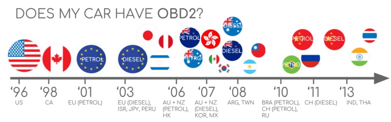 Does My Car Have OBD2
2.1. How to Determine OBD2 Compliance
Here are a few ways to determine if your car supports OBD2:
- Check the Manufacturing Year: If your car was manufactured in 1996 or later (for the US market), it most likely supports OBD2.
- Look for the OBD2 Socket: The presence of a 16-pin OBD2 socket is a strong indicator of OBD2 compliance.
- Consult the Owner’s Manual: The owner’s manual should specify whether the vehicle supports OBD2.
- Use an OBD2 Scanner: Plug an OBD2 scanner into the socket and see if it can establish a connection and read data.
2.2. Exceptions and Special Cases
While OBD2 is widely supported, there are some exceptions:
- Older Cars: Cars manufactured before 1996 may not support OBD2, although some might have an earlier OBD system (OBD1).
- Electric Vehicles (EVs): EVs often use OEM-specific UDS (Unified Diagnostic Services) communication protocols instead of OBD2.
3. OBD2 History and Evolution
The OBD2 standard evolved from earlier onboard diagnostic systems and was driven by increasing environmental regulations. The California Air Resources Board (CARB) initially required OBD systems in all new cars from 1991 for emission control.
3.1. Key Milestones in OBD2 Development
- 1991: CARB requires OBD in new cars in California.
- 1996: OBD2 becomes mandatory in the USA for cars and light trucks.
- 2001: OBD2 is required in the EU for gasoline cars.
- 2003: OBD2 is required in the EU for diesel cars (EOBD).
- 2005: OBD2 is required in the US for medium-duty vehicles.
- 2008: US cars must use ISO 15765-4 (CAN) as the OBD2 basis.
- 2010: OBD2 is required in US heavy-duty vehicles.
3.2. The Role of Standard Organizations
The Society of Automotive Engineers (SAE) played a significant role in standardizing OBD2, particularly with the SAE J1962 standard, which defines the OBD2 connector and standardized DTCs across manufacturers.
4. The Future of OBD2: Trends and Innovations
OBD2 is still relevant, but its future is evolving with new technologies and regulatory requirements. Key trends include OBD3, WWH-OBD, and OBDonUDS.
4.1. OBD3 and Telematics
OBD3 aims to enhance emission control checks through telematics. This involves equipping vehicles with a radio transponder to transmit the Vehicle Identification Number (VIN) and DTCs to a central server for monitoring.
4.2. WWH-OBD and OBDonUDS
WWH-OBD (World Wide Harmonized OBD) and OBDonUDS (OBD on UDS) seek to improve OBD communication by using the UDS protocol as a basis. These protocols streamline data access and enhance diagnostic capabilities.
4.3. Challenges in the Era of Electric Vehicles
Electric vehicles (EVs) are not always required to support OBD2, and many modern EVs use OEM-specific UDS communication, which can make it difficult to access diagnostic data.
5. OBD2 Standards: SAE J1962 and ISO 15031-3
OBD2 standards define the OBD2 connector, lower-layer protocols, and parameter IDs. The SAE J1962 standard specifies the physical connector, while the ISO 15031-3 standard is technically equivalent and used in European vehicles.
5.1. The OSI Model and OBD2 Standards
OBD2 standards can be organized using the 7-layer OSI model, which helps to understand how different protocols and standards interact:
- Application Layer: SAE J1979, ISO 15031-5
- Presentation Layer: Data encoding and decoding
- Session Layer: Establishing and managing communication sessions
- Transport Layer: ISO 15765-2 (ISO-TP)
- Network Layer: Addressing and routing of messages
- Data Link Layer: Error detection and correction
- Physical Layer: ISO 15765-4 (Diagnostics over CAN), ISO 11898 (CAN bus)
5.2. Key Differences Between SAE and ISO Standards
SAE standards are primarily used in the USA, while ISO standards are more common in Europe. For example, SAE J1979 is equivalent to ISO 15031-5, and SAE J1962 is equivalent to ISO 15031-3.
6. The OBD2 Connector: Pinout and Functionality
The OBD2 connector is a 16-pin socket that allows access to data from your car. The connector is specified in the SAE J1962 / ISO 15031-3 standards.
6.1. Pinout Diagram and Explanation
Here is an overview of the OBD2 connector pinout:
| Pin | Function |
|---|---|
| 2 | SAE J1850 PWM/VPW Bus (+) |
| 4 | Chassis Ground |
| 5 | Signal Ground |
| 6 | CAN High (ISO 15765-4) |
| 7 | ISO 9141-2 K-Line |
| 10 | SAE J1850 PWM Bus (-) |
| 14 | CAN Low (ISO 15765-4) |
| 15 | ISO 9141-2 L-Line |
| 16 | Battery Power (+12V or +24V) |
Key points to remember:
- Pin 16 supplies battery power.
- The OBD2 pinout depends on the communication protocol used by the vehicle.
- CAN bus uses pins 6 (CAN High) and 14 (CAN Low).
6.2. Type A vs. Type B Connectors
There are two main types of OBD2 connectors:
- Type A: Typically found in cars and light-duty vehicles with 12V power supply.
- Type B: Common in medium and heavy-duty vehicles with 24V power supply.
Type B connectors have an interrupted groove in the middle to prevent Type A connectors from being inserted.
7. OBD2 and CAN Bus: ISO 15765-4
Since 2008, CAN (Controller Area Network) bus has been the mandatory lower-layer protocol for OBD2 in all cars sold in the US, as per ISO 15765-4.
7.1. ISO 15765-4: Diagnostics Over CAN (DoCAN)
ISO 15765-4 defines a set of restrictions applied to the CAN standard, standardizing the interface for test equipment:
- Bit-rate: Must be either 250K or 500K.
- CAN IDs: Can be 11-bit or 29-bit.
- CAN IDs: Specific CAN IDs are used for OBD requests/responses.
- Data Length: The diagnostic CAN frame data length must be 8 bytes.
- Cable Length: The OBD2 adapter cable must be max 5 meters.
7.2. CAN Identifiers: 11-bit and 29-bit
OBD2 communication involves request and response messages. In most cars, 11-bit CAN IDs are used. The Functional Addressing ID is 0x7DF, used to ask all OBD2-compatible ECUs if they have data to report. ECUs respond with IDs 0x7E8-0x7EF, with 0x7E8 being the most common (ECM, Engine Control Module).
In some vehicles, extended 29-bit CAN identifiers are used instead. The Functional Addressing CAN ID is 0x18DB33F1. Responses use CAN IDs 0x18DAF100 to 0x18DAF1FF.
7.3. OBD2 vs. Proprietary CAN Protocols
Your car’s ECUs do not rely on OBD2 to function. Each OEM implements its own proprietary CAN protocols, specific to the vehicle brand, model, and year. OBD2 is an additional higher-layer protocol in parallel to the OEM-specific protocol.
7.4. Bit-Rate and ID Validation
OBD2 may use two bit-rates (250K, 500K) and two CAN ID lengths (11-bit, 29-bit), resulting in four potential combinations. ISO 15765-4 provides recommendations for a systematic initialization sequence to determine the correct combination.
7.5. Five Lower-Layer OBD2 Protocols
While CAN is the primary lower-layer protocol for OBD2 today, older cars may use one of the following:
- ISO 15765 (CAN bus): Mandatory in US cars since 2008.
- ISO14230-4 (KWP2000): Common for 2003+ cars in Asia.
- ISO 9141-2: Used in EU, Chrysler & Asian cars in 2000-04.
- SAE J1850 (VPW): Used mostly in older GM cars.
- SAE J1850 (PWM): Used mostly in older Ford cars.
8. Transporting OBD2 Messages via ISO-TP: ISO 15765-2
OBD2 data is communicated on the CAN bus through ISO-TP (ISO 15765-2), a transport protocol that enables communication of payloads exceeding 8 bytes. This is necessary for extracting the Vehicle Identification Number (VIN) or Diagnostic Trouble Codes (DTCs).
8.1. ISO-TP: Segmentation, Flow Control, and Reassembly
ISO 15765-2 enables segmentation, flow control, and reassembly of OBD2 messages. When data fits in a single CAN frame, ISO 15765-2 specifies the use of a ‘Single Frame’ (SF), with the first data byte containing the payload length.
9. The OBD2 Diagnostic Message: SAE J1979, ISO 15031-5
An OBD2 message consists of an identifier, data length (PCI field), and data, which is split into Mode, parameter ID (PID), and data bytes.
9.1. Example: OBD2 Request/Response for Vehicle Speed
An external tool sends a request message to the car with CAN ID 0x7DF and 2 payload bytes: Mode 0x01 and PID 0x0D. The car responds via CAN ID 0x7E8 and 3 payload bytes, including the value of Vehicle Speed in the 4th byte, 0x32 (50 in decimal form). By looking up the decoding rules for OBD2 PID 0x0D, we determine that the physical value is 50 km/h.
9.2. The 10 OBD2 Services (Modes)
There are 10 OBD2 diagnostic services (or modes):
| Mode | Description |
|---|---|
| 0x01 | Show current data |
| 0x02 | Show freeze frame data |
| 0x03 | Show stored Diagnostic Trouble Codes (DTCs) |
| 0x04 | Clear DTCs and emission-related diagnostic info |
| 0x05 | Oxygen sensor monitoring test results |
| 0x06 | Non-continuous monitoring system test results |
| 0x07 | Show pending DTCs detected during current driving cycle |
| 0x08 | Control operation of on-board system |
| 0x09 | Request vehicle information |
| 0x0A | Permanent DTCs |
Vehicles do not have to support all OBD2 modes, and they may support OEM-specific modes outside the 10 standardized modes. In OBD2 messages, the mode is in the 2nd byte. In the request, the mode is included directly (e.g., 0x01), while in the response, 0x40 is added to the mode (e.g., resulting in 0x41).
9.3. OBD2 Parameter IDs (PIDs)
Each OBD2 mode contains parameter IDs (PIDs). For example, mode 0x01 contains ~200 standardized PIDs with real-time data on speed, RPM, and fuel level. Vehicles do not have to support all OBD2 PIDs in a mode; most only support a small subset.
If an emissions-related ECU supports any OBD2 services, it must support mode 0x01 PID 0x00. In response to this PID, the vehicle ECU informs whether it supports PIDs 0x01-0x20.
10. How to Log and Decode OBD2 Data
Logging and decoding OBD2 data involves several steps: testing bit-rate, IDs, and supported PIDs; configuring OBD2 PID requests; and DBC decoding raw OBD2 data.
10.1. Testing Bit-Rate, IDs, and Supported PIDs
ISO 15765-4 describes how to determine the bit-rate and IDs used by a specific vehicle.
- Send a CAN frame at 500K and check if successful (else try 250K).
- Use the identified bit-rate for subsequent communication.
- Send multiple ‘Supported PIDs’ requests and review the results.
- Based on response IDs, determine 11-bit vs. 29-bit.
- Based on response data, see what PIDs are supported.
10.2. Configuring OBD2 PID Requests
Configure your transmit list with PIDs of interest. Consider the following:
- CAN IDs: Shift to ‘Physical Addressing’ request IDs (e.g., 0x7E0) to avoid multiple responses to each request.
- Spacing: Add 300-500 ms between each OBD2 request to avoid overwhelming the ECUs.
- Battery Drain: Use triggers to stop transmitting when the vehicle is inactive.
- Filters: Add filters to only record OBD2 responses.
10.3. DBC Decoding Raw OBD2 Data
To analyze and visualize data, you need to decode the raw OBD2 data into physical values. The necessary decoding information can be found in ISO 15031-5/SAE J1979.
Decoding OBD2 data is more complex than regular CAN signals because different OBD2 PIDs are transported using the same CAN ID (e.g., 0x7E8). You must leverage the CAN ID, OBD2 mode, and OBD2 PID to identify the signal. This is a form of multiplexing called ‘extended multiplexing’.
 OBD2 data decoded visual plot asammdf CAN bus DBC file
11. OBD2 Multi-Frame Examples: ISO-TP
OBD2 data is communicated using ISO-TP (transport protocol) as per ISO 15765-2. Here are some examples of multi-frame communication.
11.1. Example 1: OBD2 Vehicle Identification Number (VIN)
To extract the Vehicle Identification Number (VIN) from a vehicle using OBD2 requests, use mode 0x09 and PID 0x02:
- The tester tool sends a Single Frame request with the PCI field (0x02), request service identifier (0x09), and PID (0x02).
- The vehicle responds with a First Frame containing the PCI, length (0x014 = 20 bytes), mode (0x49, i.e., 0x09 + 0x40), and PID (0x02).
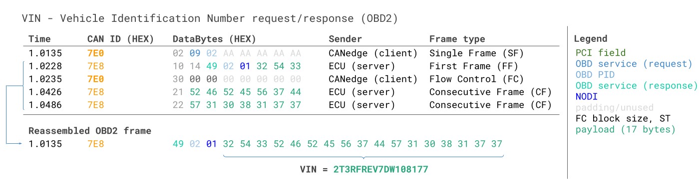 VIN Vehicle Identification Number OBD2 Example multi-frame
11.2. Example 2: OBD2 Multi-PID Request (6x)
External tools can request up to 6 mode 0x01 OBD2 PIDs in a single request frame. The ECU responds with data for supported PIDs, leaving unsupported PIDs out of the response.
11.3. Example 3: OBD2 Diagnostic Trouble Codes (DTCs)
Use OBD2 to request emissions-related Diagnostic Trouble Codes (DTCs) using mode 0x03, i.e., ‘Show stored Diagnostic Trouble Codes’. The targeted ECU(s) respond with the number of DTCs they have stored, with each DTC taking up 2 data bytes.
12. OBD2 Data Logging: Use Case Examples
OBD2 data from cars and light trucks can be used in various applications:
12.1. Logging Data from Cars
OBD2 data can be used to reduce fuel costs, improve driving habits, test prototype parts, and for insurance purposes.
12.2. Real-Time Car Diagnostics
OBD2 interfaces can stream human-readable OBD2 data in real-time for diagnosing vehicle issues.
12.3. Predictive Maintenance
Cars and light trucks can be monitored via IoT OBD2 loggers in the cloud to predict and avoid breakdowns. According to a study by McKinsey, predictive maintenance can reduce maintenance costs by up to 40%.
12.4. Vehicle Blackbox Logger
An OBD2 logger can serve as a ‘blackbox’ for vehicles, providing data for disputes or diagnostics.
13. Practical Applications of OBD2 Data
OBD2 data offers a wealth of information that can be applied in various practical scenarios, benefiting both vehicle owners and automotive professionals.
13.1. Enhancing Vehicle Performance
By monitoring real-time data such as engine RPM, throttle position, and fuel consumption, drivers can optimize their driving habits to improve fuel efficiency and reduce wear and tear on the vehicle. For example, maintaining a steady speed and avoiding harsh acceleration can significantly improve gas mileage.
13.2. Improving Fuel Efficiency
OBD2 data can be used to identify inefficiencies in a vehicle’s performance, such as a malfunctioning oxygen sensor or a clogged air filter. Addressing these issues can lead to significant improvements in fuel economy. According to the U.S. Department of Energy, properly inflated tires can improve gas mileage by up to 3%.
13.3. Diagnostic Accuracy and Speed
For automotive technicians, OBD2 data provides valuable insights into the health of a vehicle, allowing for faster and more accurate diagnoses. Access to DTCs and real-time sensor data can help pinpoint the root cause of a problem, reducing diagnostic time and improving overall efficiency.
13.4. Preventative Maintenance
OBD2 data can also be used for preventative maintenance, helping vehicle owners identify potential problems before they lead to costly repairs. Regular monitoring of key parameters can reveal trends and anomalies that indicate the need for maintenance or repairs.
13.5. Fleet Management
Fleet managers can leverage OBD2 data to monitor the performance and maintenance needs of their vehicles. This can help optimize routes, reduce fuel costs, and schedule maintenance proactively, minimizing downtime and improving overall fleet efficiency.
14. Choosing the Right OBD2 Scanner
Selecting the appropriate OBD2 scanner is crucial for effectively diagnosing and maintaining vehicles. Different scanners offer varying capabilities, so it’s important to choose one that meets your specific needs.
14.1. Basic OBD2 Scanners
Basic OBD2 scanners are designed for reading and clearing DTCs. These scanners are typically affordable and easy to use, making them ideal for vehicle owners who want to perform basic diagnostics.
14.2. Advanced OBD2 Scanners
Advanced OBD2 scanners offer more comprehensive features, such as real-time data streaming, bidirectional control, and advanced diagnostic capabilities. These scanners are better suited for professional technicians and serious DIYers who need more in-depth diagnostic information.
14.3. Features to Consider
When choosing an OBD2 scanner, consider the following features:
- Compatibility: Ensure the scanner is compatible with your vehicle’s make and model.
- Ease of Use: Look for a scanner with a user-friendly interface and clear instructions.
- Data Streaming: Real-time data streaming allows you to monitor vehicle performance in real-time.
- Bidirectional Control: Bidirectional control enables you to command the vehicle’s systems to perform specific actions for diagnostic purposes.
- Software Updates: Regular software updates ensure the scanner is up-to-date with the latest vehicle models and diagnostic protocols.
15. Common Issues and Troubleshooting with OBD2 Sockets
While OBD2 sockets are designed to be reliable, they can sometimes encounter issues. Understanding these common problems and how to troubleshoot them can save time and frustration.
15.1. Damaged or Corroded Connectors
The pins in the OBD2 socket can become damaged or corroded over time, leading to poor connections and communication errors. Regularly inspect the socket and clean the pins with a contact cleaner to ensure a good connection.
15.2. Blown Fuses
The OBD2 socket is typically powered by a fuse in the vehicle’s electrical system. If the scanner is not receiving power, check the fuse and replace it if necessary.
15.3. Software Compatibility Issues
Sometimes, the OBD2 scanner may not be compatible with the vehicle’s software, leading to communication errors. Ensure the scanner is compatible with your vehicle’s make, model, and year.
15.4. Communication Errors
Communication errors can occur if there is interference or a problem with the vehicle’s communication network. Try resetting the scanner and the vehicle’s ignition, and ensure all connections are secure.
15.5. Seeking Professional Help
If you are unable to resolve the issue on your own, seek help from a professional automotive technician. They have the expertise and tools to diagnose and repair more complex OBD2 socket issues.
16. The Role of CAR-DIAGNOSTIC-TOOL.EDU.VN in OBD2 Diagnostics
CAR-DIAGNOSTIC-TOOL.EDU.VN stands out as a premier resource, offering comprehensive support and solutions related to OBD2 diagnostics. With a focus on providing accessible, reliable, and cutting-edge information, CAR-DIAGNOSTIC-TOOL.EDU.VN is dedicated to empowering both automotive professionals and vehicle owners.
16.1. Comprehensive Diagnostic Tools
CAR-DIAGNOSTIC-TOOL.EDU.VN offers a wide range of diagnostic tools tailored to meet different needs. From basic code readers to advanced diagnostic platforms, these tools are designed for accuracy, efficiency, and ease of use. Each tool is backed by detailed documentation and technical support, ensuring users can confidently tackle any diagnostic challenge.
16.2. Expert Repair Guides
Navigating the complexities of automotive repair can be daunting. CAR-DIAGNOSTIC-TOOL.EDU.VN simplifies this process with expertly crafted repair guides. These guides provide step-by-step instructions, clear visuals, and troubleshooting tips, enabling users to accurately diagnose and fix vehicle issues. Whether it’s a minor fix or a major overhaul, these guides are invaluable resources.
16.3. Remote Technical Assistance
Sometimes, even the most skilled technicians encounter problems that require specialized expertise. CAR-DIAGNOSTIC-TOOL.EDU.VN offers remote technical assistance, connecting users with experienced professionals who can provide real-time support. This service ensures that users can overcome obstacles quickly and effectively, minimizing downtime and maximizing productivity.
16.4. Technician Training Programs
To stay competitive in the rapidly evolving automotive industry, continuous learning is essential. CAR-DIAGNOSTIC-TOOL.EDU.VN provides technician training programs designed to equip professionals with the latest knowledge and skills. These programs cover a wide range of topics, including advanced diagnostics, electric vehicle technology, and data analysis.
16.5. Why Choose CAR-DIAGNOSTIC-TOOL.EDU.VN
- Reliability: CAR-DIAGNOSTIC-TOOL.EDU.VN is known for providing accurate, up-to-date information and dependable tools.
- Accessibility: The platform is designed to be user-friendly, making it easy for both professionals and hobbyists to find the resources they need.
- Comprehensive Support: From detailed guides to remote assistance, CAR-DIAGNOSTIC-TOOL.EDU.VN offers complete support at every step.
- Cutting-Edge Knowledge: The platform keeps pace with the latest advancements in automotive technology, ensuring users are always informed.
Whether you are a seasoned mechanic, a fleet manager, or a vehicle owner passionate about understanding your car, CAR-DIAGNOSTIC-TOOL.EDU.VN is your reliable ally. Join the community today and see the impact of having access to top-notch diagnostic tools, expert guides, and support.
17. Maximizing Your Investment in Automotive Diagnostics
Effectively leveraging diagnostic tools and resources can lead to cost savings, enhanced efficiency, and improved customer satisfaction. Here are some tips to maximize your investment:
17.1. Regular Training and Skill Development
The automotive industry is constantly evolving, and technicians need to stay updated with the latest technologies and diagnostic methods. Invest in regular training programs to enhance your team’s skills and knowledge.
17.2. Efficient Workflow Management
Optimize your workshop’s workflow to minimize diagnostic time and maximize productivity. Ensure your technicians have easy access to the tools and resources they need.
17.3. Leveraging Data Analytics
Use data analytics to identify trends, predict maintenance needs, and optimize vehicle performance. Data-driven insights can help you make informed decisions and improve your bottom line.
17.4. Customer Education and Communication
Educate your customers about the benefits of regular diagnostics and preventative maintenance. Transparent communication can build trust and foster long-term relationships.
18. Common Diagnostic Trouble Codes (DTCs)
Understanding common Diagnostic Trouble Codes (DTCs) is essential for effective vehicle diagnostics and repair. These codes provide valuable insights into the issues affecting a vehicle and guide technicians in troubleshooting and resolving problems.
18.1. P0300: Random/Multiple Cylinder Misfire Detected
This DTC indicates that the engine is experiencing misfires in one or more cylinders. Misfires can be caused by a variety of factors, including faulty spark plugs, ignition coils, fuel injectors, or vacuum leaks.
18.2. P0171: System Too Lean (Bank 1)
This code indicates that the engine is running lean, meaning there is too much air and not enough fuel in the air-fuel mixture. Common causes include vacuum leaks, a malfunctioning mass airflow sensor, or a clogged fuel filter.
18.3. P0420: Catalyst System Efficiency Below Threshold (Bank 1)
This DTC indicates that the catalytic converter is not functioning efficiently. The catalytic converter is responsible for reducing harmful emissions, and a faulty converter can lead to increased pollution and reduced engine performance.
18.4. P0301: Cylinder 1 Misfire Detected
This code specifically indicates a misfire in cylinder 1. As with P0300, the misfire can be caused by issues with the spark plug, ignition coil, fuel injector, or compression in that cylinder.
18.5. P0011: “A” Camshaft Position – Timing Over-Advanced or System Performance (Bank 1)
This DTC indicates an issue with the camshaft timing. It suggests that the camshaft is more advanced than it should be, which can affect engine performance and fuel efficiency.
18.6. P0113: Intake Air Temperature Sensor 1 Circuit High
This code indicates a problem with the intake air temperature sensor circuit. The sensor measures the temperature of the air entering the engine, and a malfunction can affect the engine’s air-fuel mixture and overall performance.
19. Real-World Success Stories with Advanced Automotive Diagnostics
Advanced automotive diagnostics can lead to significant improvements in efficiency, accuracy, and customer satisfaction. Here are some real-world examples of how CAR-DIAGNOSTIC-TOOL.EDU.VN has helped automotive professionals achieve success:
19.1. Fleet Optimization for a Logistics Company
A logistics company in California was struggling with high maintenance costs and frequent breakdowns in its fleet of delivery vans. By implementing advanced diagnostic tools from CAR-DIAGNOSTIC-TOOL.EDU.VN, the company was able to identify and address potential issues before they led to costly repairs. The result was a 20% reduction in maintenance costs and a 15% increase in vehicle uptime.
19.2. Enhanced Diagnostic Accuracy for an Independent Repair Shop
An independent repair shop in Texas was looking for ways to improve its diagnostic accuracy and reduce diagnostic time. By using CAR-DIAGNOSTIC-TOOL.EDU.VN’s advanced diagnostic platform, the shop was able to pinpoint the root cause of complex vehicle issues more quickly and accurately. This led to a 30% reduction in diagnostic time and a 25% increase in customer satisfaction.
19.3. Success in Automotive Education
An automotive training institute in Michigan needed to equip its students with the latest diagnostic skills and knowledge. By partnering with CAR-DIAGNOSTIC-TOOL.EDU.VN, the institute was able to provide its students with access to state-of-the-art diagnostic tools and training programs. This has resulted in higher graduation rates and improved job placement for its students.
20. FAQs About OBD2 Sockets and Automotive Diagnostics
Here are some frequently asked questions about OBD2 sockets and automotive diagnostics.
20.1. What is an OBD2 socket?
An OBD2 socket is a standardized interface in vehicles that provides access to the vehicle’s self-diagnostic system. It allows technicians to retrieve diagnostic trouble codes (DTCs) and real-time data parameters.
20.2. Where is the OBD2 socket located in my car?
The OBD2 socket is typically located under the dashboard on the driver’s side, near the steering column or inside the center console. Consult your owner’s manual for specific instructions.