Want to understand When Was Obd2 Mandatory? OBD2, or On-Board Diagnostics II, became mandatory in specific years for different types of vehicles and regions. This guide from CAR-DIAGNOSTIC-TOOL.EDU.VN dives into the history, standards, and future of OBD2, providing you with the knowledge and tools to diagnose and repair vehicles efficiently. We offer comprehensive solutions including diagnostic tools, step-by-step repair guides, and remote technical support to enhance your skills and service quality, alongside technician training and remote support.
Contents
- 1. Understanding OBD2: The Basics
- 2. Is My Car OBD2 Compliant?
- 3. The History of OBD2: A Timeline
- 4. The Future of OBD2: What’s Next?
- 4.1. Electric Vehicles and OBD2
- 4.2. Modern Alternatives: WWH-OBD and OBDonUDS
- 4.3. The Advent of OBD3
- 4.4. Concerns About Third-Party Data Access
- 5. OBD2 Standards: A Deep Dive
- 5.1. The OSI Model
- 5.2. The OBD2 Connector: SAE J1962
- 5.3. OBD2 Connector – Type A vs. B
- 6. OBD2 and CAN Bus: ISO 15765-4
- 6.1. OBD2 CAN Identifiers (11-bit, 29-bit)
- 6.2. OBD2 vs. Proprietary CAN Protocols
- 6.3. Bit-Rate and ID Validation
- 6.4. Five Lower-Layer OBD2 Protocols
- 7. Transporting OBD2 Messages via ISO-TP: ISO 15765-2
- 8. The OBD2 Diagnostic Message: SAE J1979, ISO 15031-5
- 8.1. Example: OBD2 Request/Response
- 8.2. The 10 OBD2 Services (aka Modes)
- 8.3. OBD2 Parameter IDs (PID)
- 8.4. Tip: OBD2 PID Overview Tool
- 9. How to Log and Decode OBD2 Data
- 9.1. Test Bit-Rate, IDs & Supported PIDs
- 9.2. Configure OBD2 PID Requests
- 9.3. DBC Decode Raw OBD2 Data
- 10. OBD2 Multi-Frame Examples: ISO-TP
- 10.1. Example 1: OBD2 Vehicle Identification Number (VIN)
- 10.2. Example 2: OBD2 Multi-PID Request (6x)
- 10.3. Example 3: OBD2 Diagnostic Trouble Codes (DTCs)
- 11. OBD2 Data Logging – Use Case Examples
- FAQ: Common Questions About OBD2
1. Understanding OBD2: The Basics
OBD2 is your car’s built-in self-diagnostic system, a standardized protocol that enables the extraction of diagnostic trouble codes (DTCs) and real-time data via the OBD2 connector. Ever seen the malfunction indicator light on your dashboard? That’s your car signaling an issue. Mechanics use an OBD2 scanner, connecting it to the OBD2 16-pin connector to send requests and receive responses containing data like speed, fuel level, or DTCs, speeding up troubleshooting.
The malfunction indicator light, often called the check engine light, alerts drivers to potential issues detected by the OBD2 system.
2. Is My Car OBD2 Compliant?
Likely, if it’s a newer, non-electric car. Most support OBD2 and run on CAN bus. Older cars with a 16-pin OBD2 connector might not fully support OBD2. To determine compliance, consider where and when the vehicle was bought new.
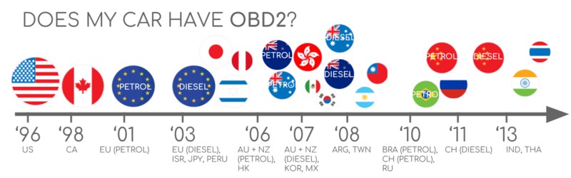
 Does My Car Have OBD2?
A graphic illustrating the years when OBD2 compliance became mandatory in the US and EU for various vehicle types.
3. The History of OBD2: A Timeline
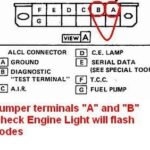
OBD2 originated in California. The California Air Resources Board (CARB) mandated OBD in all new cars from 1991 for emission control. The Society of Automotive Engineers (SAE) recommended the OBD2 standard, standardizing DTCs and the OBD connector across manufacturers (SAE J1962). From there, the OBD2 standard rolled out step-by-step.
- 1996: OBD2 became mandatory in the USA for cars/light trucks.
- 2001: Required in the EU for gasoline cars.
- 2003: Required in the EU for diesel cars (EOBD).
- 2005: OBD2 required in the US for medium-duty vehicles.
- 2008: US cars must use ISO 15765-4 (CAN) as the OBD2 basis.
- 2010: OBD2 required in US heavy-duty vehicles.
The evolution of OBD2, initially focused on emission control, has led to its current role in providing access to comprehensive vehicle data via the CAN bus.
A visual timeline illustrating the key milestones in the history of OBD2 implementation across different regions and vehicle types.
4. The Future of OBD2: What’s Next?
OBD2 is here to stay, but in what form? Let’s explore important trends.
4.1. Electric Vehicles and OBD2
Legislated OBD2 was designed for emissions control/testing. As a result, electric vehicles aren’t required to support OBD2 in any form. Almost none of the modern EVs support standard OBD2 requests, instead utilizing OEM-specific UDS communication. It’s generally impossible to decode data from these electric vehicles, except where decoding rules have been reverse engineered, as demonstrated in CAR-DIAGNOSTIC-TOOL.EDU.VN case studies for electric cars including Tesla, Hyundai/Kia, Nissan and VW/Skoda EVs.
4.2. Modern Alternatives: WWH-OBD and OBDonUDS
Today, OBD2 is implemented in various ways with limitations in data richness and lower-layer protocols. In response, modern alternatives like WWH-OBD (World Wide Harmonized OBD) and OBDonUDS (OBD on UDS) have been developed. Both enhance OBD communication by leveraging the UDS protocol as a basis.
4.3. The Advent of OBD3
In today’s world of connected cars, manual emission control checks are time-consuming and expensive. The solution? OBD3 – adding telematics to all cars. OBD3 adds a small radio transponder to all cars, allowing the car’s VIN and DTCs to be sent via WiFi to a central server for checks. While this saves cost and is convenient, it also poses political challenges due to surveillance concerns.
4.4. Concerns About Third-Party Data Access
The OBD2 protocol was originally designed for stationary emission controls. Today, OBD2 is used extensively by 3rd parties for generating real-time data. The German car industry is looking to change this, arguing that OBD was designed for repair shops, not to allow third parties to build a data-driven economy. The proposal is to turn off the OBD2 functionality while driving, collecting data in a central server, putting manufacturers in control of automotive big data. This raises security concerns and may disrupt the market for OBD2 3rd party services.
The transition to electric vehicles is influencing the future of OBD, with some manufacturers potentially restricting access to vehicle data through the OBD2 port.
5. OBD2 Standards: A Deep Dive
On-board diagnostics, OBD2, is a higher-layer protocol. CAN is a method for communication. This makes OBD2 comparable to other CAN-based higher-layer protocols like J1939, CANopen, and NMEA 2000. The OBD2 standards specify the OBD2 connector, lower-layer protocols, and OBD2 parameter IDs (PID).
5.1. The OSI Model
The standards can be displayed in a 7-layer OSI model. Several layers are covered by both SAE and ISO standards, reflecting standards for OBD defined in the USA (SAE) and the EU (ISO). Several standards are technically equivalent, for example, SAE J1979 vs. ISO 15031-5 and SAE J1962 vs. ISO 15031-3.
The relationship between OBD2 and CAN bus, highlighting the ISO standards that define the communication protocols.
5.2. The OBD2 Connector: SAE J1962
The 16-pin OBD2 connector lets you easily access data from your car. It’s specified in the standard SAE J1962 / ISO 15031-3. Here are a few things to note.
- The connector is near your steering wheel but may be hidden.
- Pin 16 supplies battery power (often while the ignition is off).
- The OBD2 pinout depends on the communication protocol.
- The most common lower-layer protocol is CAN bus, meaning pins 6 (CAN-H) and 14 (CAN-L) will typically be connected.
A detailed diagram of the OBD2 connector pinout, highlighting the purpose of each pin, including power supply and communication channels.
5.3. OBD2 Connector – Type A vs. B
In practice, you may encounter both type A and type B OBD2 connectors. Type A is typically found in cars, while type B is common in medium and heavy-duty vehicles. The two types share similar OBD2 pinouts but provide different power supply outputs (12V for type A and 24V for type B). The baud rate often differs as well, with cars typically using 500K, while most heavy-duty vehicles use 250K (more recently with support for 500K). Type B OBD2 connector has an interrupted groove in the middle. A type B OBD2 adapter cable will be compatible with both types A and B, while a type A will not fit into a type B socket.
A comparison of OBD2 connector types A and B, highlighting their physical differences and voltage outputs for different vehicle categories.
6. OBD2 and CAN Bus: ISO 15765-4
Since 2008, CAN bus has been the mandatory lower-layer protocol for OBD2 in all cars sold in the US as per ISO 15765. ISO 15765-4 (aka Diagnostics over CAN or DoCAN) refers to restrictions applied to the CAN standard (ISO 11898). Specifically, it standardizes the CAN interface for test equipment, focusing on the physical, data link, and network layers.
- The CAN bus bit-rate must be either 250K or 500K.
- The CAN IDs can be 11-bit or 29-bit.
- Specific CAN IDs are used for OBD requests/responses.
- The diagnostic CAN frame data length must be 8 bytes.
- The OBD2 adapter cable must be max 5 meters.
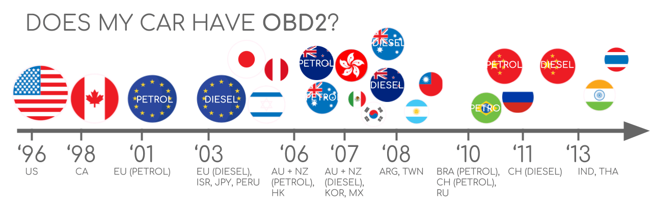
6.1. OBD2 CAN Identifiers (11-bit, 29-bit)
All OBD2 communication involves request/response messages. In most cars, 11-bit CAN IDs are used for OBD2 communication. The Functional Addressing ID is 0x7DF, corresponding to asking all OBD2 compatible ECUs if they have data to report on the requested parameter. CAN IDs 0x7E0-0x7E7 can be used to perform Physical Addressing requests from specific ECUs (less commonly used). ECUs can respond with 11-bit IDs 0x7E8-0x7EF. The most common response ID is 0x7E8 (ECM, Engine Control Module) and 0x7E9 (TCM, Transmission Control Module).
In some vehicles (e.g., vans and light/medium/heavy-duty vehicles), you may find OBD2 communication uses extended 29-bit CAN identifiers instead of 11-bit CAN identifiers. Here, the Functional Addressing CAN ID is 0x18DB33F1. If the vehicle responds, you will see responses with CAN IDs 0x18DAF100 to 0x18DAF1FF. The response ID is also sometimes shown in the ‘J1939 PGN’ form, specifically the PGN 0xDA00 (55808), which in the J1939-71 standard is marked as ‘Reserved for ISO 15765-2’.
A visual representation of OBD2 request and response frames, showing the structure of data parameters and identifiers.
 OBD2 OBD CAN bus Identifiers 7DF 7E8 7E0
6.2. OBD2 vs. Proprietary CAN Protocols
Your car’s electronic control units (ECUs) do not rely on OBD2 to function. Each original equipment manufacturer (OEM) implements their own proprietary CAN protocols for this purpose, specific to the vehicle brand, model, and year. If you are not the OEM, you will normally not be able to interpret this data unless you can reverse engineer it. If you connect a CAN bus data logger to your car’s OBD2 connector, you may see the OEM-specific CAN data, typically broadcast at a rate of 1000-2000 frames/second. However, many newer cars use a gateway that blocks access to this CAN data, only enabling OBD2 communication via the OBD2 connector. Think of OBD2 as an ‘extra’ higher-layer protocol in parallel to the OEM-specific protocol.
The distinction between OBD2 and OEM-specific CAN bus data, highlighting the limited access to proprietary data without reverse engineering.
6.3. Bit-Rate and ID Validation
OBD2 may use one of two bit-rates (250K, 500K) and one of two CAN ID lengths (11-bit, 29-bit), resulting in 4 potential combinations. In modern cars, 500K and 11-bit IDs are the most common. ISO 15765-4 provides recommendations for performing a systematic initialization sequence to determine the relevant combination, leveraging that OBD2 compliant vehicles must respond to a specific mandatory OBD2 request. Newer versions of ISO 15765-4 consider that vehicles may support OBD communication via OBDonUDS rather than OBDonEDS. OBDonEDS (aka OBD2, SAE OBD, EOBD or ISO OBD) is used in most non-EV cars today, while WWH-OBD is primarily used in EU trucks/buses.
A flowchart detailing the process of validating OBD2 bit-rate and CAN ID to ensure proper communication with the vehicle’s diagnostic system.
6.4. Five Lower-Layer OBD2 Protocols
CAN today serves as the lower-layer basis for OBD2 in the vast majority of cars as per ISO 15765. However, if you inspect an older car (pre 2008), it is useful to know the other four lower-layer protocols that have been used as the basis for OBD2.
- ISO 15765 (CAN bus): Mandatory in US cars since 2008 and used in the vast majority of cars today.
- ISO14230-4 (KWP2000): The Keyword Protocol 2000 was a common protocol for 2003+ cars in Asia.
- ISO 9141-2: Used in EU, Chrysler & Asian cars in 2000-04.
- SAE J1850 (VPW): Used mostly in older GM cars.
- SAE J1850 (PWM): Used mostly in older Ford cars.
The five lower-layer OBD2 protocols, including CAN bus and older standards like KWP2000 and SAE J1850, with their respective standards and usage timelines.
7. Transporting OBD2 Messages via ISO-TP: ISO 15765-2
All OBD2 data is communicated on the CAN bus through a transport protocol called ISO-TP (ISO 15765-2), enabling communication of payloads exceeding 8 bytes. This is necessary in OBD2 when extracting the Vehicle Identification Number (VIN) or Diagnostic Trouble Codes (DTCs). ISO 15765-2 enables segmentation, flow control, and reassembly. Often, the OBD2 data will fit in a single CAN frame. ISO 15765-2 specifies the use of a ‘Single Frame’ (SF), implying that the 1st data byte (aka PCI field) contains the payload length (excluding padding), leaving 7 bytes for the OBD2 related communication.
Different frame types used in ISO 15765-2 for transporting OBD2 messages, including single frame, first frame, consecutive frame, and flow control frame.
8. The OBD2 Diagnostic Message: SAE J1979, ISO 15031-5
To better understand OBD2 on CAN, consider a raw ‘Single Frame’ OBD2 CAN message. An OBD2 message comprises an identifier, data length (PCI field), and data. The data is split into Mode, parameter ID (PID), and data bytes.
8.1. Example: OBD2 Request/Response
Consider this example request/response for the parameter ‘Vehicle Speed’. An external tool sends a request message to the car with CAN ID 0x7DF and 2 payload bytes: Mode 0x01 and PID 0x0D. The car responds via CAN ID 0x7E8 and 3 payload bytes, including the value of Vehicle Speed in the 4th byte, 0x32 (50 in decimal form). By looking up the decoding rules for OBD2 PID 0x0D, we determine that the physical value is 50 km/h.
The structure of an OBD2 message, breaking down the components such as mode, parameter ID (PID), and data bytes.
An example of an OBD2 request and response sequence for vehicle speed, illustrating the CAN IDs and payload bytes.
A specific example of OBD2 PID 0x0D for vehicle speed, detailing the data encoding and physical value interpretation.
8.2. The 10 OBD2 Services (aka Modes)
There are 10 OBD2 diagnostic services (or modes). Mode 0x01 shows current real-time data, while others are used to show/clear diagnostic trouble codes (DTCs) or show freeze frame data. Vehicles do not have to support all OBD2 modes and may support modes outside the 10 standardized modes (aka OEM-specific OBD2 modes). In OBD2 messages, the mode is in the 2nd byte. In the request, the mode is included directly (e.g., 0x01), while in the response, 0x40 is added to the mode (e.g., resulting in 0x41).
The 10 OBD2 diagnostic services (modes), outlining their functions, such as displaying real-time data, trouble codes, and freeze frame data.
8.3. OBD2 Parameter IDs (PID)
Each OBD2 mode contains parameter IDs (PIDs). Mode 0x01 contains ~200 standardized PIDs with real-time data on speed, RPM, and fuel level. However, a vehicle does not have to support all OBD2 PIDs in a mode. Most vehicles only support a small subset. If an emissions-related ECU supports any OBD2 services, then it must support mode 0x01 PID 0x00. In response to this PID, the vehicle ECU informs whether it supports PIDs 0x01-0x20. PID 0x00 is useful as a fundamental ‘OBD2 compatibility test’. Further, PIDs 0x20, 0x40, …, 0xC0 can be used to determine support for the remaining mode 0x01 PIDs.
8.4. Tip: OBD2 PID Overview Tool
In the appendices of SAE J1979 and ISO 15031-5, you will find scaling info for standard OBD2 PIDs, which allows you to decode the data into physical values. Check out our OBD2 PID overview tool at CAR-DIAGNOSTIC-TOOL.EDU.VN, which helps you construct OBD2 request frames and dynamically decode the OBD2 responses.
A visual representation of OBD2 request and response frames, showing the structure of data parameters and identifiers.
 OBD2 PID overview tool
9. How to Log and Decode OBD2 Data
Let’s explore a practical example of logging OBD2 data with the CANedge CAN bus data logger. The CANedge lets you configure custom CAN frames to be transmitted for OBD2 logging. Connect the device to your vehicle via our OBD2-DB9 adapter cable available at CAR-DIAGNOSTIC-TOOL.EDU.VN.
9.1. Test Bit-Rate, IDs & Supported PIDs
ISO 15765-4 describes how to determine which bit-rate and IDs are used by a specific vehicle. Test this with the CANedge:
- Send a CAN frame at 500K and check if successful (else try 250K).
- Use the identified bit-rate for subsequent communication.
- Send multiple ‘Supported PIDs’ requests and review the results.
- Based on response IDs, you can determine 11-bit vs. 29-bit.
- Based on response data, you can see what PIDs are supported.
Most 2008+ non-EV cars support 40-80 PIDs via 500K bit-rate, 11-bit CAN IDs, and the OBD2/OBDonEDS protocol. It’s common to see multiple responses to a single OBD request, as we use the 0x7DF request ID, which polls all ECUs for a response.
The connection setup for OBD2 data logging, highlighting the data logger and the request/response sequence with CAN IDs.
 OBD2 bit rate test
 OBD2 Supported PIDs Test
 Review supported PIDs via OBD2 lookup tool
9.2. Configure OBD2 PID Requests
Now, you know which OBD2 PIDs are supported by your vehicle and what bit-rate and CAN IDs to use when requesting them. Configure your transmit list with PIDs of interest.
- CAN IDs: Shift to Physical Addressing request IDs (e.g., 0x7E0) to avoid multiple responses to each request.
- Spacing: Add 300-500 ms between each OBD2 request (spamming the ECUs may cause them not to respond).
- Battery Drain: Use triggers to stop transmitting when the vehicle is inactive (to avoid waking up ECUs).
- Filters: Add filters to only record OBD2 responses (e.g., if your vehicle also outputs OEM-specific CAN data).
 obd2-transmit-list-example-canedge
9.3. DBC Decode Raw OBD2 Data
Finally, to analyze/visualize your data, you need to decode the raw OBD2 data into physical values. The necessary decoding information can be found in ISO 15031-5/SAE J1979. We provide a free OBD2 DBC file that makes it easy to DBC decode raw OBD2 data in most CAN bus software tools. Decoding OBD2 data is more complex than regular CAN signals. Different OBD2 PIDs are transported using the same CAN ID (e.g., 0x7E8). As such, the CAN ID is not sufficient to uniquely identify what signals are encoded in the payload. Leverage the CAN ID, OBD2 mode, and OBD2 PID to identify the signal. This is a form of multiplexing referred to as ‘extended multiplexing’, which can be implemented in DBC files.
 OBD2 data decoded visual plot asammdf CAN bus DBC file
10. OBD2 Multi-Frame Examples: ISO-TP
All OBD2 data is communicated using the ISO-TP (transport protocol) as per ISO 15765-2. Most examples reflect single-frame communication. Multi-frame OBD2 communication requires flow control frames. Transmit a static flow control frame 50 ms after the initial request frame. Multi-frame OBD2 responses require CAN software/API tools that support ISO-TP, like the CANedge MF4 decoders.
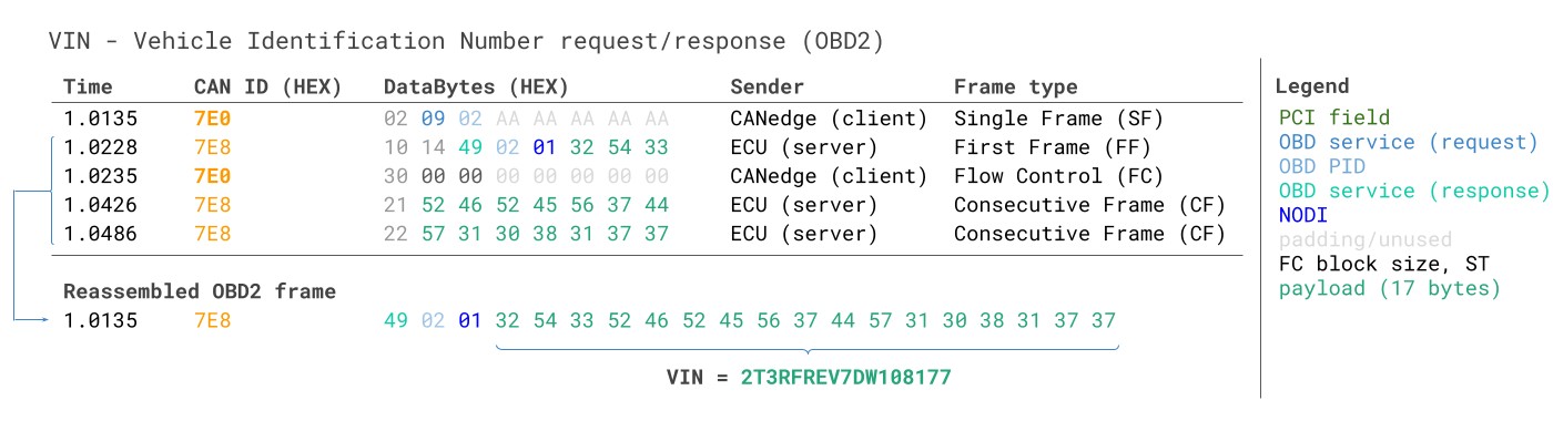
10.1. Example 1: OBD2 Vehicle Identification Number (VIN)
The Vehicle Identification Number (VIN) is relevant to telematics and diagnostics. To extract the Vehicle Identification Number from a vehicle using OBD2 requests, use mode 0x09 and PID 0x02.
 OBD2-multi-frame-request-message-vehicle-identification-number
The tester tool sends a Single Frame request with the PCI field (0x02), request service identifier (0x09), and PID (0x02). The vehicle responds with a First Frame containing the PCI, length (0x014 = 20 bytes), mode (0x49, i.e. 0x09 + 0x40), and PID (0x02). Following the PID is the byte 0x01, which is the Number Of Data Items (NODI), in this case 1. The remaining 17 bytes equal the VIN and can be translated from HEX to ASC via methods discussed in our intro to UDS.
 VIN Vehicle Identification Number OBD2 Example multi-frame
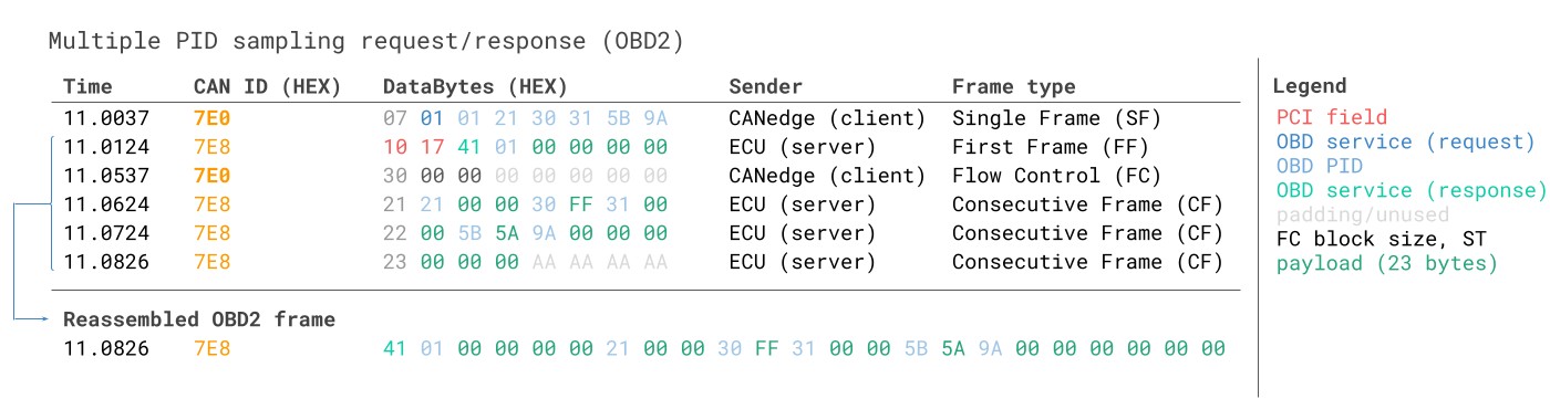
10.2. Example 2: OBD2 Multi-PID Request (6x)
External tools can request up to 6 mode 0x01 OBD2 PIDs in a single request frame. The ECU responds with data for supported PIDs. This feature lets you collect OBD2 data at higher frequency and efficiency. The signal encoding is specific to your request method, making the use of generic OBD2 DBC files difficult.
 Requesting multiple PIDs in one request
10.3. Example 3: OBD2 Diagnostic Trouble Codes (DTCs)
Use OBD2 to request emissions-related Diagnostic Trouble Codes (DTCs) using mode 0x03, i.e., ‘Show stored Diagnostic Trouble Codes’. The targeted ECU(s) will respond with the number of DTCs stored, with each DTC taking up 2 data bytes. Multi-frame responses are necessary when more than 2 DTCs are stored. The 2-byte DTC value is split into two parts, with the first 2 bits defining the ‘category’ and the remaining 14 bits defining a 4-digit code. Decoded DTC values can be looked up in various OBD2 DTC lookup tools like repairpal.com.
The interpretation of diagnostic trouble codes (DTCs) in OBD2, showing the breakdown of the code into category and specific code values.
 OBD2 Diagnostic Trouble Codes DTC CAN Bus Request Response Example
11. OBD2 Data Logging – Use Case Examples
OBD2 data from cars and light trucks can be used in various use cases.
- Logging data from cars: Reduce fuel costs, improve driving, test prototype parts, and insurance.
- Real-time car diagnostics: Stream human-readable OBD2 data in real-time for diagnosing vehicle issues.
- Predictive maintenance: Monitor cars and light trucks via IoT OBD2 loggers in the cloud to predict and avoid breakdowns.
- Vehicle black box logger: An OBD2 logger can serve as a ‘black box’ for vehicles, providing data for disputes or diagnostics.
An illustration representing the use of an OBD2 data logger in a car, highlighting its role in vehicle diagnostics and data collection.
Real-time diagnostics through OBD2 data streaming, showcasing the potential for immediate analysis and troubleshooting.
Predictive maintenance using OBD2 data loggers, enabling proactive vehicle monitoring and breakdown prevention through telematics.
A CAN bus data logger functioning as a vehicle black box, providing valuable data for insurance purposes and warranty validation.
FAQ: Common Questions About OBD2
- When did OBD2 become mandatory in the USA?
OBD2 was mandated in 1996 for all cars and light trucks sold in the USA. This requirement ensured standardized emission control diagnostics. - Is OBD2 required for electric vehicles?
No, OBD2 is not typically required for electric vehicles as it was primarily designed for emission control in combustion engine vehicles. - What is the difference between OBD2 and CAN bus?
OBD2 is a diagnostic protocol, while CAN bus is a communication standard. OBD2 uses CAN bus as one of its lower-layer protocols for data transmission. - What are the main OBD2 modes or services?
The main OBD2 modes include displaying current data (Mode 01), showing freeze frame data, clearing trouble codes, and requesting diagnostic trouble codes (DTCs). - How can I determine if my car supports OBD2?
Check the vehicle’s manufacturing year and region. Most vehicles manufactured after 1996 in the USA and 2001 in the EU support OBD2. Also, look for the standard 16-pin OBD2 connector. - What is the purpose of the OBD2 PID 0x00?
OBD2 PID 0x00 is used to determine which PIDs (Parameter IDs) are supported by the vehicle’s ECU (Engine Control Unit). It acts as a compatibility test for OBD2 functionality. - What is ISO 15765-4 and why is it important?
ISO 15765-4, also known as Diagnostics over CAN (DoCAN), standardizes the CAN interface for test equipment. It specifies parameters like bit-rate, CAN IDs, and data length. - How do I decode raw OBD2 data into physical values?
Use an OBD2 DBC file along with CAN bus software tools to decode raw OBD2 data into physical values. This involves converting hexadecimal values to meaningful units like km/h or degrees Celsius. - What are the benefits of using a CANedge data logger for OBD2 data?
CANedge allows you to configure custom CAN frames, test bit-rates, and log OBD2 data directly to an SD card. It offers a flexible and efficient way to record and analyze